Torque on Rotated Circular Loop in Field of Opposite Parallel Wires
As illustrated in the diagram, a circular conducting loop of radius lies in the plane of the paper along with two long parallel wires (labeled 1 and 2). Both wires are situated at a distance from the center of the loop. Each wire as well as the circular loop carries an identical current . Looking from above, the current circulating in the loop flows in the counterclockwise direction.
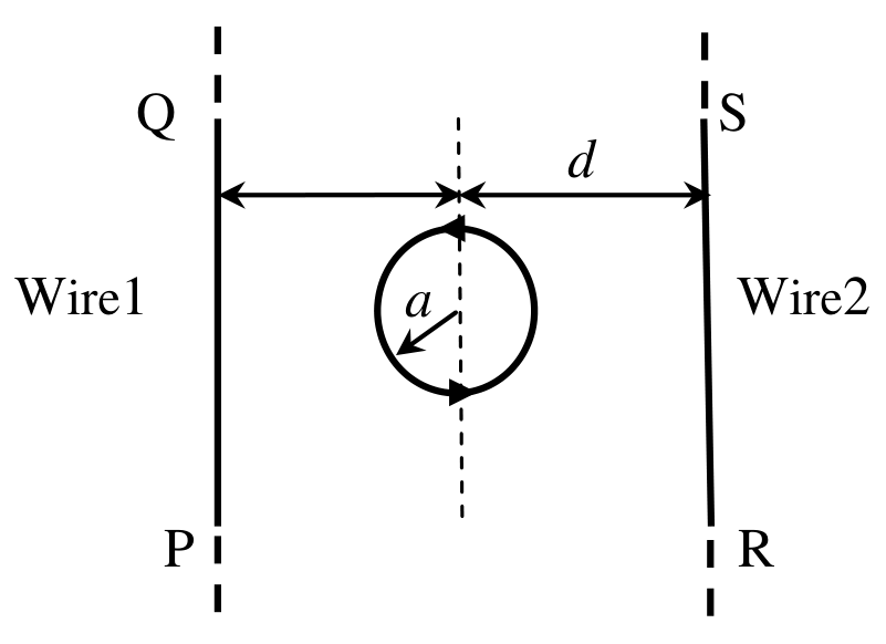
Assuming , the circular loop is rotated through an angle of about a diametrical axis parallel to the straight wires, starting from the configuration shown. If the currents through the two wires flow in mutually opposite directions, determine the torque acting on the loop in this new orientation (take the magnetic field generated by the wires to be uniform over the region of the loop).
Options
Topics & Concepts
Step-by-Step Solution
To find the torque acting on the circular loop in its rotated orientation, we follow these steps:
1. Magnetic Field Due to the Two Wires
Let the plane of the paper be the -plane, with the center of the circular loop at the origin . The two long parallel wires lie parallel to the -axis at positions (Wire 1) and (Wire 2).
Since the currents through the two wires flow in mutually opposite directions, let the current in Wire 1 be in the -direction () and the current in Wire 2 be in the -direction ().
Using the Biot-Savart law (or Ampere's law) for an infinitely long straight wire, the magnetic field produced by each wire at the origin is:
- Due to Wire 1 at :
- Due to Wire 2 at :
Since , the magnetic field over the region of the loop can be considered uniform and is given by the superposition of the fields from both wires:
The magnitude of the net magnetic field is:
2. Magnetic Dipole Moment of the Loop
The circular loop carries a current in the counterclockwise direction when viewed from above (along the -axis), meaning its initial magnetic dipole moment vector points perpendicular to the plane of the paper along the -direction:
The magnitude of the magnetic moment is:
3. Torque on the Rotated Loop
The loop is rotated through an angle of about a diametrical axis parallel to the straight wires (the -axis).
Upon this rotation, the magnetic moment vector rotates by an angle of away from the -axis. Since the magnetic field is oriented along the -axis, the angle between the magnetic moment vector and the magnetic field becomes (or ).
The magnitude of the torque acting on the loop is:
Substituting the values of and :
Simplifying the expression:
Thus, the torque acting on the loop is .
Correct Option: (B)