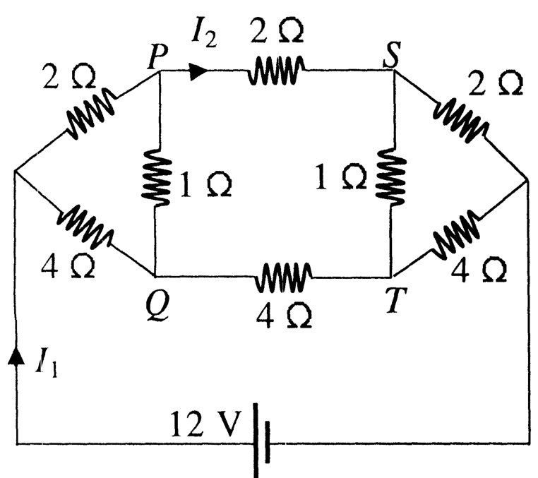
To analyze the resistance network, let us set the potential of the negative terminal (rightmost junction) as VY=0 V and the potential of the positive terminal (leftmost junction) as VX=12 V.
Let VP,VQ,VS, and VT denote the electric potentials at nodes P,Q,S, and T, respectively.
1. Nodal Equations using Kirchhoff's Current Law (KCL)
At node P:
2VP−12+1VP−VQ+2VP−VS=0
VP−6+2(VP−VQ)+VP−VS=0⟹4VP−2VQ−VS=12— (1)
At node Q:
4VQ−12+1VQ−VP+4VQ−VT=0
VQ−12+4(VQ−VP)+VQ−VT=0⟹−4VP+6VQ−VT=12— (2)
At node S:
2VS−VP+1VS−VT+2VS−0=0
VS−VP+2(VS−VT)+VS=0⟹−VP+4VS−2VT=0— (3)
At node T:
4VT−VQ+1VT−VS+4VT−0=0
VT−VQ+4(VT−VS)+VT=0⟹−VQ−4VS+6VT=0— (4)
2. Solving for Node Potentials
By bridge symmetry:
- Assume VP=VQ and VS=VT.
From equation (1):
4VP−2VP−VS=12⟹2VP−VS=12— (5)
From equation (3):
−VP+4VS−2VS=0⟹−VP+2VS=0⟹VP=2VS— (6)
Substituting equation (6) into equation (5):
2(2VS)−VS=12⟹3VS=12⟹VS=4 V
Using VS=4 V in equation (6):
VP=8 V
Thus, the node potentials are:
VP=8 V,VQ=8 V,VS=4 V,VT=4 V
Substituting these values back into equations (1)–(4) confirms that they uniquely satisfy all Kirchhoff's equations.
3. Verification of Options
-
Option (A): The electric current flowing through segment PQ is:
IPQ=1ΩVP−VQ=18−8=0 A
Therefore, Option (A) is correct.
-
Option (B): The total current I1 supplied by the 12 V battery is the sum of currents entering the top and bottom branches:
Itop=2ΩVX−VP=212−8=2 A
Ibottom=4ΩVX−VQ=412−8=1 A
I1=Itop+Ibottom=2 A+1 A=3 A
Therefore, Option (B) is correct.
-
Option (C): Potential at node S is VS=4 V, and potential at node Q is VQ=8 V. Since 4 V<8 V, the potential at S is lower than that at Q.
Therefore, Option (C) is correct.
-
Option (D): The current I2 flowing through the segment PS is:
I2=2ΩVP−VS=28−4=2 A
Therefore, Option (D) is correct.
Conclusion
Statements (A), (B), (C), and (D) are all valid.