Hall Voltage Dependence on Carrier Density and Magnetic Field
In a thin rectangular metallic conductor strip, a steady current flows along the positive -axis, as shown in the illustration. The length, width, and thickness of this strip are denoted by , , and , respectively. A uniform external magnetic field acts along the positive -direction. Consequently, the mobile charge carriers experience a transverse magnetic deflection along the -direction. This causes accumulation of charge carriers on the planar surface and induces an equal and opposite charge layer on the surface opposite to . Therefore, a potential difference develops along the -direction. The accumulation of charges persists until the transverse magnetic force is counterbalanced by the electrostatic force. Assume that the electric current is distributed uniformly across the strip's cross-section and is conducted solely by electrons.
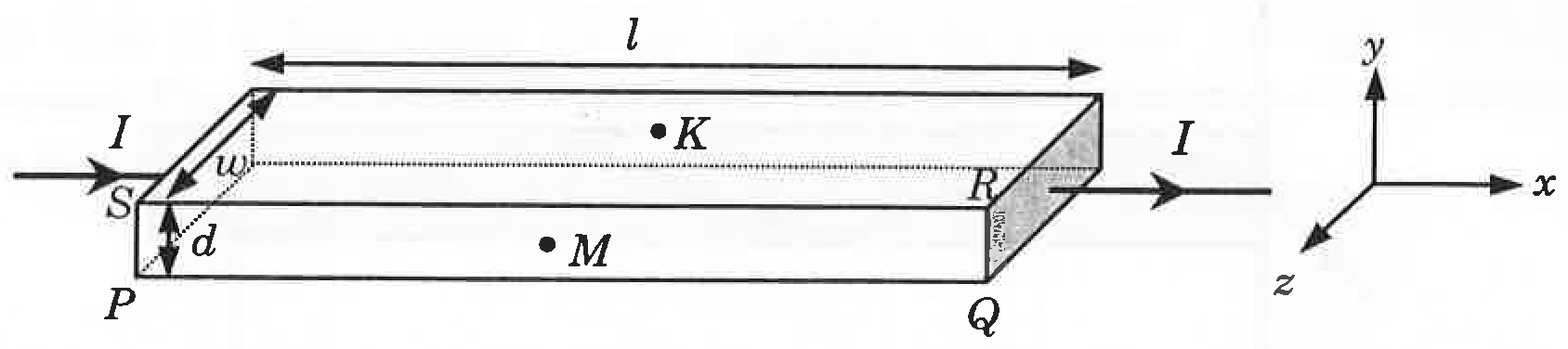
Consider two metallic strips (1 and 2) having identical geometric dimensions (length , width , and thickness ), but with carrier number densities and , respectively. Strip 1 is situated in a magnetic field and strip 2 is situated in a magnetic field , both oriented along the positive -axis. Let and denote the potential differences produced between points and in strips 1 and 2, respectively. Assuming the current passing through both strips is identical, which of the following option(s) is/are correct?
Options
If and , then
If and , then
If and , then
If and , then
Topics & Concepts
Step-by-Step Solution
To find the relationship between the potential difference (Hall voltage) and the parameters of the metallic strip, let us analyze the forces acting on the charge carriers (electrons) at steady state.
1. Drift Velocity of Charge Carriers:
The current flowing through the strip of cross-sectional area along the -direction is given by:
where:
- is the charge carrier density,
- is the elementary charge,
- is the width of the strip along the -direction,
- is the thickness of the strip along the -direction,
- is the drift velocity of the electrons.
Thus, the drift velocity is:
2. Hall Electric Field and Potential Difference:
A uniform magnetic field is applied along the -direction. The magnetic force on an electron moving with drift velocity is:
This causes accumulation of electrons along the -direction, establishing a transverse electric field until equilibrium is reached:
The potential difference developed between the two opposite faces (points and , separated by width along the -axis) is:
Substituting the value of :
From this result, we see that for fixed current and thickness :
The ratio of the potential differences and for strips 1 and 2 is:
3. Evaluation of the Options:
-
Option A: If and : (Correct)
-
Option B: If and , then . (Incorrect)
-
Option C: If and : (Correct)
-
Option D: If and , then . (Incorrect)
Conclusion:
The correct options are A and C.