Dielectric Permittivity in Switched Multi-Capacitor Circuit
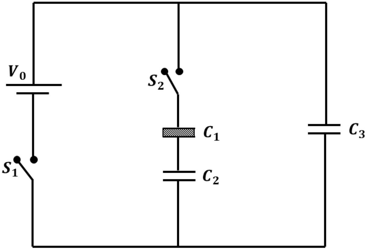
Consider three identical capacitors , and , each possessing a capacitance of , which are initially uncharged. As illustrated in the circuit diagram, they are connected to a cell of electromotive force (emf) , and capacitor is completely filled with a dielectric substance having relative permittivity . Initially, switch is closed with switch remaining open. Once capacitor achieves full charge, switch is opened and switch is concurrently closed. After the circuit settles into electrostatic equilibrium, the charge residing on is measured to be . Determine the value of .
Topics & Concepts
Step-by-Step Solution
To determine the relative permittivity , we analyze the circuit in two stages:
Stage 1: Switch is closed and is open
- Since switch is open, the middle branch containing capacitors and remains uncharged.
- Capacitor is connected directly across the cell of emf through switch .
- Given the capacitance of is , the initial charge stored on when fully charged is:
Stage 2: Switch is opened and is closed
-
Opening disconnects the cell from the circuit, isolating the charges.
-
Closing connects the series combination of capacitors and in parallel with capacitor .
-
Let be the equivalent capacitance of the series combination of and :
-
By charge conservation, the initial charge on the top plate of redistributes between and the series combination of and : where:
- is the final charge on .
- is the charge on the series branch of and .
-
Thus, the charge on the series combination is:
-
Since and the branch with are in parallel, they share the same final potential difference :
-
The equivalent capacitance can also be expressed in terms of and :
-
Equating the two expressions for :
-
Solving for :