JEE Challenger
More from Current Electricity

Conditions for Zero Current in Resistance R2 in Circuit

As depicted in the circuit diagram, two ideal batteries with emfs V1V_1 and V2V_2 are connected along with three resistors R1R_1, R2R_2, and R3R_3. The current flowing through the resistor R2R_2 will vanish under which of the following conditions?
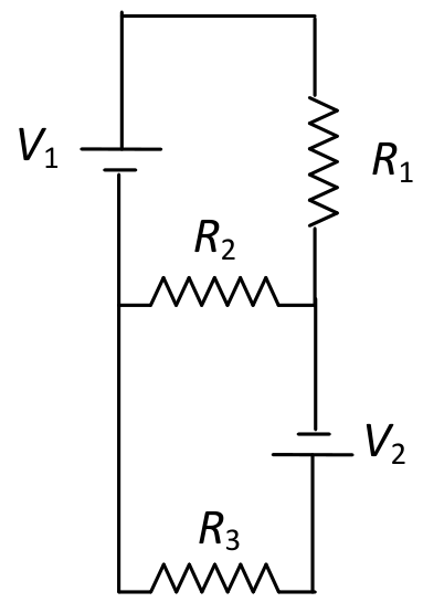
Question Diagram 1

Options

A

V1=V2 and R1=R2=R3V_1 = V_2 \text{ and } R_1 = R_2 = R_3

Correct
B

V1=V2 and R1=2R2=R3V_1 = V_2 \text{ and } R_1 = 2R_2 = R_3

Correct
C

V1=2V2 and 2R1=2R2=R3V_1 = 2V_2 \text{ and } 2R_1 = 2R_2 = R_3

D

2V1=V2 and 2R1=R2=R32V_1 = V_2 \text{ and } 2R_1 = R_2 = R_3

Correct

Step-by-Step Solution

To determine the condition under which the current flowing through resistor R2R_2 vanishes, we can perform a nodal analysis on the circuit.

1. Nodal Potential Assignment

Let us choose the wire connecting the negative terminal of V1V_1, the left terminal of R2R_2, and the left side of R3R_3 as the reference node with potential: VL=0 VV_L = 0\text{ V}

Let VRV_R be the potential at the junction to the right of R2R_2 (between R1R_1, R2R_2, and V2V_2).

  • Top Branch: The battery V1V_1 has its negative terminal connected to the reference node (0 V0\text{ V}) and its positive terminal connected to the top wire. Therefore, the potential at the top of resistor R1R_1 is +V1+V_1.
  • Middle Branch: Resistor R2R_2 is connected between potential VRV_R and 0 V0\text{ V}.
  • Bottom Branch: The battery V2V_2 has its negative terminal connected to junction RR (potential VRV_R) and its positive terminal connected towards resistor R3R_3. Thus, the potential at the junction between V2V_2 and R3R_3 is VR+V2V_R + V_2.

2. Current Expressions and Kirchhoff's Current Law (KCL)

The current flowing from the top branch into junction RR through resistor R1R_1 is: I1=V1−VRR1I_1 = \frac{V_1 - V_R}{R_1}

The current flowing through resistor R2R_2 from junction RR to junction LL is: I2=VR−0R2=VRR2I_2 = \frac{V_R - 0}{R_2} = \frac{V_R}{R_2}

The current flowing downwards from junction RR through battery V2V_2 and resistor R3R_3 to the reference node is: I3=(VR+V2)−0R3I_3 = \frac{(V_R + V_2) - 0}{R_3}

For the current through R2R_2 to be zero (I2=0I_2 = 0), the potential difference across R2R_2 must be zero: VR=0 VV_R = 0\text{ V}

Applying KCL at junction RR with VR=0 VV_R = 0\text{ V}: I1=I2+I3  ⟹  V1R1=0+V2R3I_1 = I_2 + I_3 \implies \frac{V_1}{R_1} = 0 + \frac{V_2}{R_3}

Thus, the condition for zero current in R2R_2 is independent of R2R_2 and is given by: V1R1=V2R3\frac{V_1}{R_1} = \frac{V_2}{R_3}


3. Verification of Options

  • Option A: V1=V2 and R1=R2=R3V_1 = V_2 \text{ and } R_1 = R_2 = R_3 V1R1=V2R3  ⟹  V1R1=V1R1(Satisfied)\frac{V_1}{R_1} = \frac{V_2}{R_3} \implies \frac{V_1}{R_1} = \frac{V_1}{R_1} \quad \text{(Satisfied)}

  • Option B: V1=V2 and R1=2R2=R3V_1 = V_2 \text{ and } R_1 = 2R_2 = R_3 Here R1=R3R_1 = R_3, so: V1R1=V2R3  ⟹  V1R1=V1R1(Satisfied)\frac{V_1}{R_1} = \frac{V_2}{R_3} \implies \frac{V_1}{R_1} = \frac{V_1}{R_1} \quad \text{(Satisfied)}

  • Option C: V1=2V2 and 2R1=2R2=R3V_1 = 2V_2 \text{ and } 2R_1 = 2R_2 = R_3 Here V1=2V2V_1 = 2V_2 and R3=2R1R_3 = 2R_1: V1R1=2V2R1,while V2R3=V22R1\frac{V_1}{R_1} = \frac{2V_2}{R_1}, \quad \text{while } \frac{V_2}{R_3} = \frac{V_2}{2R_1} 2V2R1≠V22R1(Not Satisfied)\frac{2V_2}{R_1} \neq \frac{V_2}{2R_1} \quad \text{(Not Satisfied)}

  • Option D: 2V1=V2 and 2R1=R2=R32V_1 = V_2 \text{ and } 2R_1 = R_2 = R_3 Here V2=2V1V_2 = 2V_1 and R3=2R1R_3 = 2R_1: V2R3=2V12R1=V1R1(Satisfied)\frac{V_2}{R_3} = \frac{2V_1}{2R_1} = \frac{V_1}{R_1} \quad \text{(Satisfied)}


Conclusion

requirements are satisfied by options A, B, and D.