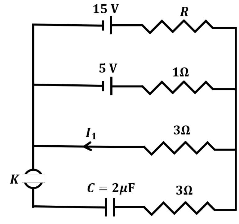
To solve the given problem, let us analyze the circuit step-by-step for t<t0 (key K open) and for t≥t0 (key K closed).
1. Circuit Analysis for t<t0 (Key K Open)
Let the right-hand vertical wire be at a reference potential of 0 V. Let VL be the potential of the left-hand vertical node.
The batteries are oriented such that their negative terminals are on the left and positive terminals are on the right.
The currents leaving the left node L through the top three branches are:
-
Branch 1 (Top branch with 15 V battery and resistance R):
Itop=RVL−(−15)=RVL+15
-
Branch 2 (Middle branch with 5 V battery and 1 Ω resistor):
I1Ω=1VL−(−5)=VL+5
-
Branch 3 (Middle branch with 3 Ω resistor):
I3Ω=3VL−0=3VL
The current I1 defined in the diagram flows to the left through the 3 Ω resistor, so:
I1=−I3Ω=−3VL
We are given that a current of 1 A flows through the 1 Ω resistor, which means:
∣I1Ω∣=∣VL+5∣=1 A
This gives two potential values for VL:
- VL+5=1⟹VL=−4 V⟹I1=34 A
- VL+5=−1⟹VL=−6 V⟹I1=2 A
From Option (B), I1=2 A, which uniquely gives:
VL=−6 V
Thus, Option (B) is correct.
2. Determination of Resistance R
Applying Kirchhoff's Current Law (KCL) at node L for t<t0:
Itop+I1Ω+I3Ω=0
RVL+15+(VL+5)+3VL=0
Substituting VL=−6 V:
R−6+15+(−6+5)+3−6=0
R9−1−2=0⟹R9=3⟹R=3 Ω
Thus, Option (A) is correct.
3. Circuit Analysis for t≥t0 (Key K Closed)
When key K is closed at t=t0, the fourth branch containing the capacitor C=2 μF and the 3 Ω resistor is connected to the circuit.
To analyze the charging process, we determine the Thevenin equivalent circuit connected across the capacitor branch:
-
Thevenin Voltage (Vth): This is the open-circuit potential difference across the left and right nodes before connecting the 4th branch:
Vth=∣VL∣=6 V
-
Thevenin Resistance (Req): The equivalent resistance of branches 1, 2, and 3 connected in parallel:
Req1=R1+11+31=31+1+31=35 Ω−1⟹Req=0.6 Ω
-
Total Resistance of the RC Loop (Rtotal):
Rtotal=Req+3 Ω=0.6 Ω+3 Ω=3.6 Ω
-
Time Constant (τ):
τ=Rtotal×C=3.6 Ω×2 μF=7.2 μs
4. Evaluation of Current at t=t0+7.2 μs
Since the capacitor is initially uncharged (VC(t0+)=0), the initial current in the capacitor at t=t0+ is:
IC(t0+)=RtotalVth=3.6 Ω6 V=35 A
The current as a function of time for t≥t0 is:
IC(t)=IC(t0+)e−τt−t0=35e−τt−t0 A
At t=t0+7.2 μs=t0+τ:
IC(t0+τ)=35e−1=35×0.36=0.60 A
Thus, Option (C) is correct.
5. Evaluation of Final Charge (t→∞)
As t→∞, the capacitor is fully charged and acts as an open circuit (IC(∞)=0). The potential difference across the capacitor reaches Vth=6 V.
The steady-state charge on the capacitor is:
Q(∞)=C⋅Vth=2 μF×6 V=12 μC
Thus, Option (D) is correct.
Conclusion
All statements (A), (B), (C), and (D) are correct.