JEE Challenger
More from Current Electricity

Power Dissipation Comparison in Circuit Configurations with Switches

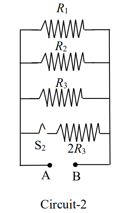
In Circuit-1 and Circuit-2 shown in the figures, R1=1 ΩR_1 = 1\ \Omega, R2=2 ΩR_2 = 2\ \Omega and R3=3 ΩR_3 = 3\ \Omega. P1P_1 and P2P_2 are the power dissipations in Circuit-1 and Circuit-2 when the switches S1\text{S}_1 and S2\text{S}_2 are in open conditions, respectively. Q1Q_1 and Q2Q_2 are the power dissipations in Circuit-1 and Circuit-2 when the switches S1\text{S}_1 and S2\text{S}_2 are in closed conditions, respectively.

Which of the following statement(s) is(are) correct?
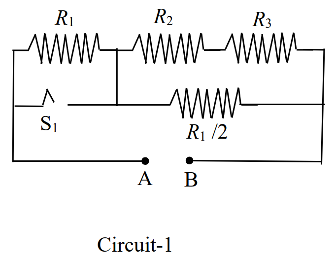
Question Diagram 1
Question Diagram 2

Options

A

When a voltage source of 6 V6\text{ V} is connected across A and B in both circuits, P1<P2P_1 < P_2.

B

When a constant current source of 2 Amp2\text{ Amp} is connected across A and B in both circuits, P1>P2P_1 > P_2.

C

When a voltage source of 6 V6\text{ V} is connected across A and B in Circuit-1, Q1>P1Q_1 > P_1.

Correct
D

When a constant current source of 2 Amp2\text{ Amp} is connected across A and B in both circuits, Q2<Q1Q_2 < Q_1.

Step-by-Step Solution

To determine the correct statement(s), we first analyze the equivalent resistance of both circuits under open and closed switch conditions.

Given: R1=1 Ω,R2=2 Ω,R3=3 ΩR_1 = 1\ \Omega, \quad R_2 = 2\ \Omega, \quad R_3 = 3\ \Omega


1. Analysis of Circuit-1

  • When switch S1\text{S}_1 is OPEN:

    • The upper branch consists of R1R_1, R2R_2, and R3R_3 connected in series: Rupper, open=R1+R2+R3=1+2+3=6 ΩR_{\text{upper, open}} = R_1 + R_2 + R_3 = 1 + 2 + 3 = 6\ \Omega
    • The middle branch has resistance R1/2=0.5 ΩR_1/2 = 0.5\ \Omega, connected in parallel with the upper branch across terminals A\text{A} and B\text{B}.
    • The net equivalent resistance R1,openR_{1,\text{open}} is: R1,open=6×0.56+0.5=36.5=613 ΩR_{1,\text{open}} = \frac{6 \times 0.5}{6 + 0.5} = \frac{3}{6.5} = \frac{6}{13}\ \Omega
  • When switch S1\text{S}_1 is CLOSED:

    • Switch S1\text{S}_1 short-circuits resistor R1R_1. The upper branch now consists of only R2R_2 and R3R_3 in series: Rupper, closed=R2+R3=2+3=5 ΩR_{\text{upper, closed}} = R_2 + R_3 = 2 + 3 = 5\ \Omega
    • The net equivalent resistance R1,closedR_{1,\text{closed}} is: R1,closed=5×0.55+0.5=2.55.5=511 ΩR_{1,\text{closed}} = \frac{5 \times 0.5}{5 + 0.5} = \frac{2.5}{5.5} = \frac{5}{11}\ \Omega

2. Analysis of Circuit-2

  • When switch S2\text{S}_2 is OPEN:

    • The active branches connected in parallel across terminals A\text{A} and B\text{B} are R1R_1, R2R_2, and R3R_3: 1R2,open=1R1+1R2+1R3=11+12+13=116 Ω−1\frac{1}{R_{2,\text{open}}} = \frac{1}{R_1} + \frac{1}{R_2} + \frac{1}{R_3} = \frac{1}{1} + \frac{1}{2} + \frac{1}{3} = \frac{11}{6}\ \Omega^{-1} R2,open=611 ΩR_{2,\text{open}} = \frac{6}{11}\ \Omega
  • When switch S2\text{S}_2 is CLOSED:

    • An additional parallel branch containing resistor 2R3=2(3)=6 Ω2R_3 = 2(3) = 6\ \Omega is included: 1R2,closed=1R2,open+12R3=116+16=126=2 Ω−1\frac{1}{R_{2,\text{closed}}} = \frac{1}{R_{2,\text{open}}} + \frac{1}{2R_3} = \frac{11}{6} + \frac{1}{6} = \frac{12}{6} = 2\ \Omega^{-1} R2,closed=12 ΩR_{2,\text{closed}} = \frac{1}{2}\ \Omega

3. Verification of the Options

  • Option (A): Voltage source of V=6 VV = 6\text{ V} connected across A and B in both circuits when switches are open. P1=V2R1,open=626/13=78 WP_1 = \frac{V^2}{R_{1,\text{open}}} = \frac{6^2}{6/13} = 78\text{ W} P2=V2R2,open=626/11=66 WP_2 = \frac{V^2}{R_{2,\text{open}}} = \frac{6^2}{6/11} = 66\text{ W} Since P1=78 W>P2=66 WP_1 = 78\text{ W} > P_2 = 66\text{ W}, statement (A) (P1<P2P_1 < P_2) is incorrect.

  • Option (B): Constant current source of I=2 AI = 2\text{ A} connected across A and B in both circuits when switches are open. P1=I2R1,open=22×613=2413 W≈1.85 WP_1 = I^2 R_{1,\text{open}} = 2^2 \times \frac{6}{13} = \frac{24}{13}\text{ W} \approx 1.85\text{ W} P2=I2R2,open=22×611=2411 W≈2.18 WP_2 = I^2 R_{2,\text{open}} = 2^2 \times \frac{6}{11} = \frac{24}{11}\text{ W} \approx 2.18\text{ W} Since P1<P2P_1 < P_2, statement (B) (P1>P2P_1 > P_2) is incorrect.

  • Option (C): Voltage source of V=6 VV = 6\text{ V} connected across A and B in Circuit-1. P1=78 WP_1 = 78\text{ W} Q1=V2R1,closed=625/11=3965=79.2 WQ_1 = \frac{V^2}{R_{1,\text{closed}}} = \frac{6^2}{5/11} = \frac{396}{5} = 79.2\text{ W} Since Q1=79.2 W>P1=78 WQ_1 = 79.2\text{ W} > P_1 = 78\text{ W}, statement (C) (Q1>P1Q_1 > P_1) is correct.

  • Option (D): Constant current source of I=2 AI = 2\text{ A} connected across A and B in both circuits when switches are closed. Q1=I2R1,closed=22×511=2011 W≈1.82 WQ_1 = I^2 R_{1,\text{closed}} = 2^2 \times \frac{5}{11} = \frac{20}{11}\text{ W} \approx 1.82\text{ W} Q2=I2R2,closed=22×12=2 WQ_2 = I^2 R_{2,\text{closed}} = 2^2 \times \frac{1}{2} = 2\text{ W} Since Q2=2 W>Q1=2011 WQ_2 = 2\text{ W} > Q_1 = \frac{20}{11}\text{ W}, statement (D) (Q2<Q1Q_2 < Q_1) is incorrect.


Conclusion

The only correct statement is (C).

Power Dissipation Comparison in Circuit Configurations with Switches | Physics PYQ Solution - JEE Challenger