Match AC and DC Circuit Voltage and Current Relationships
You are given many resistances, capacitors and inductors. These are connected to variable DC voltage source (the first two circuits) or an AC voltage source of 50 Hz frequency (the next three circuits) in different ways as shown in Column II. When a current (steady state for DC or rms for AC) flows through the circuit, the corresponding voltage and (indicated in circuits) are related as shown in Column I. Match the two.
Column I
(A) is proportional to
(B)
(C)
(D) is proportional to
Column II
(p)
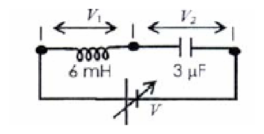
(q)
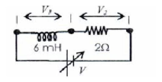
(r)
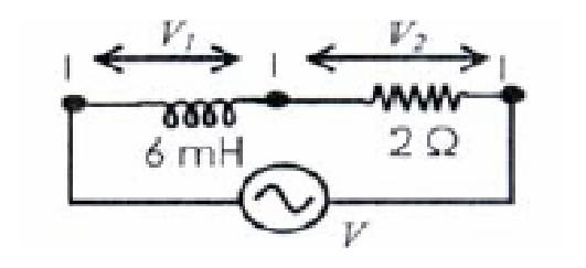
(s)
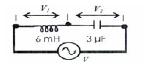
(t)
Options
ACorrect
A: r and s and t
BCorrect
B: q and r and s and t
CCorrect
C: p and q
DCorrect
D: q and r and s and t
Topics & Concepts
Step-by-Step Solution
To determine the correct matching between Column I and Column II, we analyze the behavior of each circuit in Column II:
Analysis of Circuit (p)
- Components: Inductor () and Capacitor () connected in series to a variable DC voltage source .
- In steady-state DC, the capacitor acts as an open circuit (blocks DC), so the current through the circuit is:
- Since no current flows, the voltage drop across the inductor is:
- The entire source voltage appears across the capacitor:
- Therefore, circuit (p) satisfies C ().
Analysis of Circuit (q)
- Components: Inductor () and Resistor () connected in series to a variable DC voltage source .
- In steady-state DC, the inductor acts as an ideal short circuit (zero resistance):
- The steady-state current is:
- The voltage across the resistor is:
- Thus:
- and , which matches C.
- Since and , we have , which matches B.
- Since , is proportional to , which matches D.
- Therefore, circuit (q) matches B, C, D.
Analysis of Circuit (r)
- Components: Inductor () and Resistor () connected to an AC source of frequency .
- Angular frequency:
- Reactance of the inductor:
- Resistance:
- Since :
- Here, , and:
- (matches A)
- (matches B)
- (matches D)
- Therefore, circuit (r) matches A, B, D.
Analysis of Circuit (s)
- Components: Inductor () and Capacitor () connected to an AC source of frequency .
- Reactance of the inductor:
- Reactance of the capacitor:
- Clearly, , which implies:
- Here, , and:
- (matches A)
- (matches B)
- (matches D)
- Therefore, circuit (s) matches A, B, D.
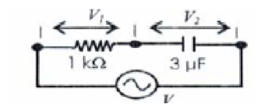
Analysis of Circuit (t)
- Components: Resistor () and Capacitor () connected to an AC source of frequency .
- Resistance:
- Reactance of the capacitor:
- Since :
- Here, , and:
- (matches A)
- (matches B)
- (matches D)
- Therefore, circuit (t) matches A, B, D.
Conclusion and Final Matching
- A r, s, t
- B q, r, s, t
- C p, q
- D q, r, s, t