Internal Resistance Measurement Using Meter Bridge Setup
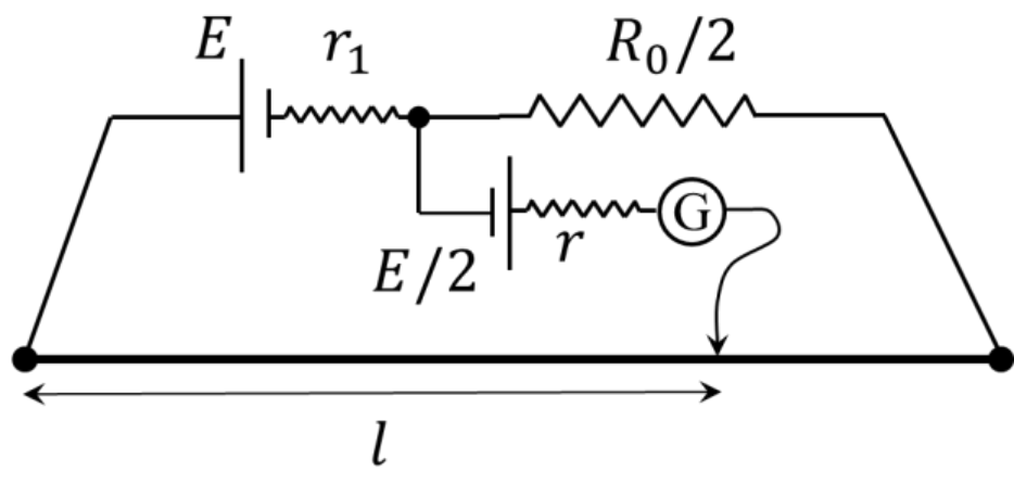
To find the internal resistance of a battery having emf , a meter bridge having wire resistance , an auxiliary resistance , a secondary cell with emf (having internal resistance ), and a galvanometer G are connected as illustrated in the circuit diagram. If the balance point is detected at , evaluate the value of in .
Topics & Concepts
Step-by-Step Solution
To find the internal resistance of the cell, we analyze the circuit under the condition of zero current through the galvanometer (null point).
1. Primary Circuit Analysis
The primary circuit forms a single closed loop consisting of:
- A cell of emf with internal resistance
- An auxiliary resistance of
- The meter bridge wire of resistance and length
The total resistance of the primary circuit loop is:
The current flowing through the primary circuit loop is:
2. Resistance of the Wire Segment
The resistance of the wire segment of length from the left end to the jockey position is:
3. Potential Difference and Balance Condition
Let be the electric potential at the left terminal of the meter bridge wire.
-
The potential at the balance point along the wire is:
-
Let be the node between internal resistance and auxiliary resistance . The potential at node is related to through the upper left branch:
-
The potential difference between point and node is:
At the balance point, no current flows through the galvanometer branch. Therefore, the potential difference across this branch must equal the emf of the secondary cell :
Equating both expressions for :
4. Calculation of
Substitute into the balance equation:
Canceling from both sides:
Substitute and :
Final Answer: The value of is .