Intensity Pattern in Youngs Double Slit Experiment Variant
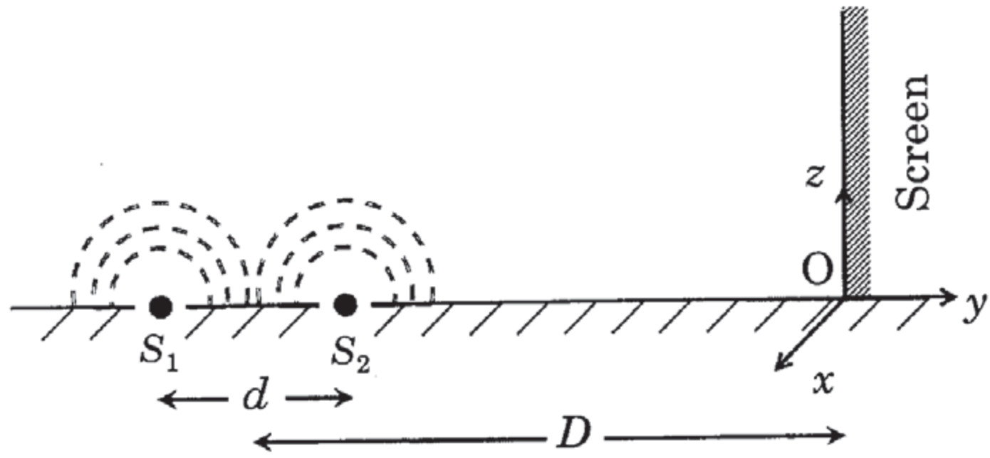
In a modified Young's double slit setup, two small pinholes acting as coherent point sources () with wavelength are placed in an opaque sheet lying in the plane. A observing screen is placed parallel to the plane (for ) at a distance from the midpoint of , as shown schematically in the figure. The separation distance between the sources is . The origin lies at the intersection of the screen and the line joining . Which of the following assertions is(are) true regarding the intensity pattern formed on the screen?
Options
Straight bright and dark fringes parallel to the -axis
The region very close to the point will be dark
Hyperbolic bright and dark fringes with foci symmetrically placed about in the -direction
Semi circular bright and dark fringes centered at point
Topics & Concepts
Step-by-Step Solution
To determine the nature and characteristics of the intensity pattern formed on the screen, we analyze the setup using a 3D Cartesian coordinate system.
1. Geometry of the Setup and Fringe Shape
Let the midpoint of the line segment be the origin .
- The line joining the two coherent sources and lies along the -axis. Therefore, the coordinates of the sources are:
- The observing screen is parallel to the plane located at , restricted to .
- The point is the intersection of the screen and the -axis, so its coordinates are .
For any point on the screen (), the distances and are:
Let be the radial distance of point from the point on the screen. The path difference between the waves arriving at point is:
Notice that depends solely on . For constant path difference (and hence uniform intensity), must be constant:
Since , this equation represents concentric semicircles centered at point . Thus, the intensity pattern consists of semi-circular bright and dark fringes centered at point . This confirms Option D.
2. Intensity at the Region Near Point
At the point , we have . The path difference at simplifies to:
Given values:
Calculating the ratio of path difference to wavelength:
Therefore, the path difference at is:
This corresponds precisely to the condition for destructive interference. Consequently, the region very close to the point will be dark. This confirms Option B.
Final Conclusion
- Option B is CORRECT.
- Option D is CORRECT.