Induced EMF in Two Connected Rotating Wire Loops
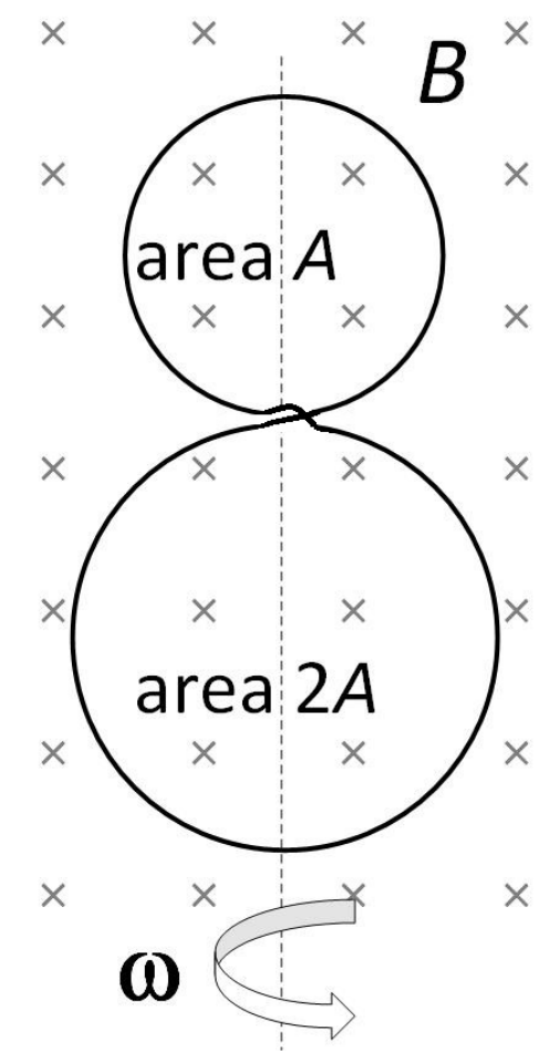
An insulated circular wire made of copper is twisted into two distinct loop regions having surface areas and , as depicted in the figure. The wires remain electrically insulated from each other at their crossing point. The entire loop assembly lies in the plane of the paper. A constant magnetic field is directed perpendicularly into the plane of the page. At time , the structure begins to rotate around its common diameter with a steady angular velocity in the field. Select the correct statement(s):
Options
The total induced across the system is proportional to the summation of the individual areas of both loops.
The amplitude of the peak net induced generated by both loops combined equals the peak induced amplitude of the smaller loop on its own.
The net generated across both loops varies proportionally with .
The rate at which magnetic flux changes reaches a maximum when the plane of the loops becomes perpendicular to the plane of the paper.
Topics & Concepts
Step-by-Step Solution
To analyze the induced electromotive force () in the system, we trace the continuous path of the twisted wire loop.
1. Circuit Topology and Magnetic Flux
The circular wire is twisted into a "figure-8" shape consisting of two distinct loops of surface areas and . Because the wire crosses over itself at the intersection point while remaining electrically insulated, tracing the current along the single continuous wire loop reveals that if the traversal direction is clockwise in one loop, it must be counter-clockwise in the other loop.
Consequently, the normal vectors to the surfaces of the two loops point in opposite directions with respect to the path of the current:
At , the plane of the loops lies in the plane of the paper, and the uniform magnetic field points perpendicularly into the plane of the page. As the system rotates about its common diameter with a constant angular velocity , the angle between the surface normal of each loop and the magnetic field vector at time is .
Taking the sense of traversal into account, the total magnetic flux linked with the continuous wire loop at any time is the algebraic difference of the fluxes through the two individual loop regions:
2. Induced Electromotive Force ()
By Faraday's Law of Electromagnetic Induction, the net induced () in the wire loop is:
3. Evaluation of the Options
-
Option A: The net depends on the effective net area , which is proportional to the difference between the individual areas of the two loops, not their summation . Thus, Option A is incorrect.
-
Option B:
- The peak (amplitude) of the net induced is:
- The peak induced for the smaller loop (area ) acting alone would be: Since , the amplitude of the maximum net induced equals that of the smaller loop alone. Thus, Option B is correct.
-
Option C: The net induced varies as , not . Thus, Option C is incorrect.
-
Option D: The magnitude of the rate of change of flux is given by: This magnitude reaches its maximum value () when , corresponding to . At , the plane of the loops has rotated by from its initial position, making the plane of the loops perpendicular to the plane of the paper. Thus, Option D is correct.
Conclusion
The correct options are B and D.