Analysis of AC Circuit with Resistor Inductor and Capacitor
Consider the circuit shown where , , and are connected in series with an alternating source . Identify the correct option(s) from the following:
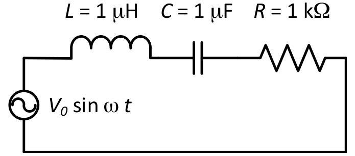
Options
The current will be in phase with the voltage if
The frequency at which the current will be in phase with the voltage is independent of
At the current flowing through the circuit becomes nearly zero
At , the circuit behaves like a capacitor
Topics & Concepts
Step-by-Step Solution
To determine the correct options, let us analyze the series circuit driven by an alternating voltage source .
1. Resonance Frequency and Phase Condition
For the current to be in phase with the applied voltage, the net reactance of the circuit must be zero. This occurs at the resonant angular frequency :
Solving for :
Given values:
Substituting these values into the resonance equation:
- Option A: Claims current is in phase with voltage at . Since , Option A is incorrect.
- Option B: The expression is entirely independent of the resistance . Therefore, Option B is correct.
2. Behavior at Low Frequencies ()
The total impedance of a series circuit is given by:
As :
The peak current amplitude is:
Since , the current amplitude . Thus, at frequencies close to zero, the current flowing through the circuit becomes nearly zero. Therefore, Option C is correct.
3. Behavior at High Frequencies ()
At angular frequencies much larger than the resonant frequency ():
- Inductive reactance:
- Capacitive reactance:
Since , the inductive reactance dominates over the capacitive reactance. Hence, the circuit behaves like an inductive circuit (inductor), not a capacitor. Therefore, Option D is incorrect.
Conclusion
The correct options are B and C.