Effective Numerical Aperture of Two Optical Fibers Joined Longitudinally
Light guidance within an optical fiber can be understood by considering a structure comprising a thin solid glass cylinder of refractive index surrounded by a cladding medium of lower refractive index . Light propagation occurs due to successive total internal reflections at the core-cladding interface as illustrated in the figure. All rays entering with an incident angle less than a maximum limiting value are guided within the core of refractive index . The numerical aperture (NA) of the structure is defined by .
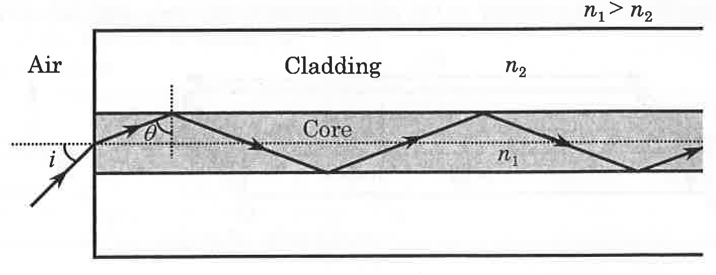
Suppose two structures possessing the identical cross-sectional area, but with differing numerical apertures and (), are joined longitudinally end-to-end. The numerical aperture of the combined fiber structure is
Options
Topics & Concepts
Step-by-Step Solution
To find the numerical aperture of the combined optical fiber structure, let us recall the definition and working principle of an optical fiber:
-
Condition for Total Internal Reflection (TIR): Consider a light ray entering the core of refractive index from air () at an angle of incidence . By Snell's law at the entrance face: where is the angle of refraction inside the core with respect to the fiber axis.
The ray strikes the core-cladding interface at an angle of incidence . For total internal reflection to occur at the core-cladding interface (where the cladding has refractive index with ), the angle must be greater than or equal to the critical angle :
Squaring both sides and using :
Substituting this back into Snell's law at the entrance face:
Thus, the maximum angle of incidence is given by: where is the numerical aperture of the optical fiber.
-
Propagation through the Combined Structure: When two optical fibers with numerical apertures and are joined longitudinally end-to-end, light must propagate successfully through both sections without leaking into the cladding.
- For light to be guided through the first structure, the condition is:
- For light to also be guided through the second structure, the ray's angle with respect to the axis must be confined such that total internal reflection occurs in the second structure as well, which requires:
For light to be guided through the entire length of the combined fiber structure, it must satisfy both conditions simultaneously:
Since it is given that :
Therefore, the numerical aperture of the combined fiber structure is .
Correct Option: (D)