Correct Circuit for Verification of Ohms Law
To verify Ohm's law, a student is provided with a test resistor , a high resistance , a small resistance , two identical galvanometers and , and a variable voltage source . The correct circuit to carry out the experiment is
Options
A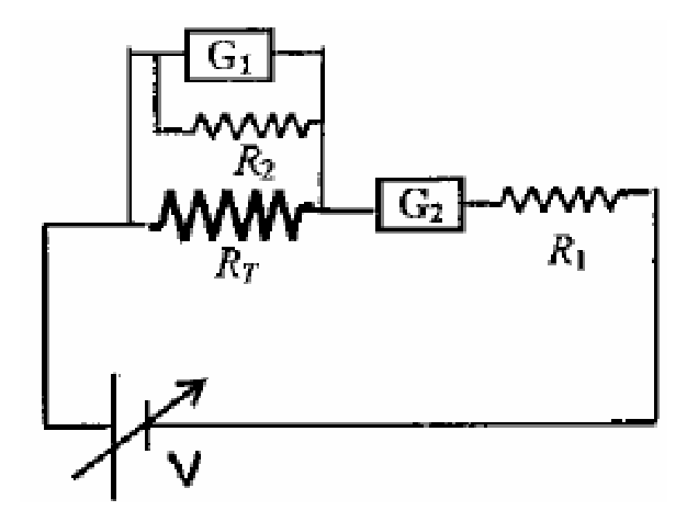
B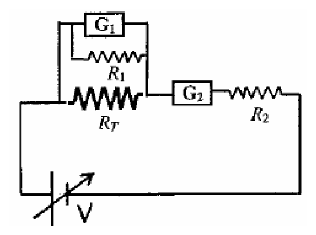
C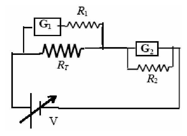 Correct
D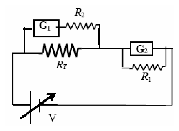
Topics & Concepts
Step-by-Step Solution
To verify Ohm's law for a test resistor , one needs to measure:
- The potential difference across the test resistor using a voltmeter.
- The current flowing through the circuit (and hence through the test resistor) using an ammeter.
Conversion of a Galvanometer into a Voltmeter:
A voltmeter must have a very high resistance so that it draws negligible current from the circuit when connected across a component.
- A galvanometer is converted into a voltmeter by connecting a large (high) resistance in series with it.
- Given that is a high resistance, the voltmeter combination consists of galvanometer connected in series with .
- This voltmeter combination must be connected in parallel with the test resistor .
Conversion of a Galvanometer into an Ammeter:
An ammeter must have a very low resistance so that it does not significantly alter the total resistance of the circuit when connected.
- A galvanometer is converted into an ammeter by connecting a small resistance (shunt) in parallel with it.
- Given that is a small resistance, the ammeter combination consists of galvanometer connected in parallel with .
- This ammeter combination must be connected in series with the test resistor .
Circuit Analysis of Option C:
- Across the test resistor , the galvanometer is connected in series with the high resistance (forming an ideal voltmeter in parallel with ).
- In series with the test resistor , the galvanometer is shunted with the small resistance (forming an ammeter in series with ).
- The entire arrangement is connected to the variable voltage source .
Thus, the circuit shown in Option C correctly configures the measuring instruments to verify Ohm's law.
Therefore, the correct option is C.