Comparison of Power Dissipation in Three Resistor Configurations
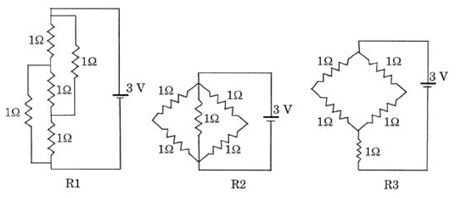
Figure shows three resistor configurations R1, R2 and R3 connected to battery. If the power dissipated by the configuration R1, R2 and R3 is P1, P2 and P3, respectively, then
Options
A
B
C
Correct
D
Topics & Concepts
Step-by-Step Solution
To determine the correct relationship between the powers dissipated by the three configurations, we find the equivalent resistance of each circuit connected across the battery. The power dissipated in each case is given by:
1. Configuration :
- The circuit is a symmetric Wheatstone bridge consisting of five resistors.
- The four outer arms each have resistance , and the central resistor has resistance .
- The ratio of the resistances of opposite arms is balanced:
- Therefore, the potential difference across the central resistor is zero, and no current flows through it.
- The remaining four resistors form two parallel branches, each having two resistors in series:
- The equivalent resistance of configuration is:
- The power dissipated in configuration is:
2. Configuration :
- Configuration consists of a four-resistor bridge network connected in series with an additional resistor at the bottom.
- The upper diamond bridge consists of two parallel branches, each with two resistors in series:
- This bridge is in series with the bottom resistor:
- The power dissipated in configuration is:
3. Configuration :
- By analyzing the node connections of configuration :
- The parallel and series combinations of the five resistors reduce to an equivalent resistance of:
- The parallel and series combinations of the five resistors reduce to an equivalent resistance of:
- The power dissipated in configuration is:
Comparison:
Comparing the power dissipated in the three configurations:
Thus:
Therefore, the correct option is (C).