JEE Challenger
More from Electrostatic Potential and Capacitance

Charge Distribution on Capacitors in Steady State Circuit

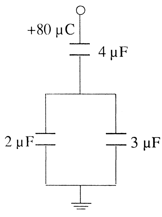
In the circuit shown below, a total charge of +80 μC+80\ \mu\text{C} is supplied to the top plate of the 4 μF4\ \mu\text{F} capacitor. In the steady state condition, determine the charge on the upper plate of the 3 μF3\ \mu\text{F} capacitor.

Question Diagram 1

Options

A

+32 μC+32\ \mu\text{C}

B

+40 μC+40\ \mu\text{C}

C

+48 μC+48\ \mu\text{C}

Correct
D

+80 μC+80\ \mu\text{C}

Step-by-Step Solution

To find the charge on the upper plate of the 3 μF3\ \mu\text{F} capacitor in the steady state, we analyze the charge distribution on the isolated portion of the circuit.

Step 1: Identify the Isolated Node

The node connected to:

  1. The bottom plate of the 4 μF4\ \mu\text{F} capacitor,
  2. The top plate of the 2 μF2\ \mu\text{F} capacitor, and
  3. The top plate of the 3 μF3\ \mu\text{F} capacitor

forms an isolated conductor system (an isolated "island") that is not connected to any external voltage source directly. By the principle of conservation of charge, the total net charge on this isolated island must be zero (assuming it was initially uncharged):

qbottom,4μF+qtop,2μF+qtop,3μF=0q_{\text{bottom}, 4\mu\text{F}} + q_{\text{top}, 2\mu\text{F}} + q_{\text{top}, 3\mu\text{F}} = 0

Step 2: Induced Charge on the 4 μF4\ \mu\text{F} Capacitor

A charge of +80 μC+80\ \mu\text{C} is supplied to the top plate of the 4 μF4\ \mu\text{F} capacitor. By electrostatic induction, an equal and opposite charge of −80 μC-80\ \mu\text{C} is induced on the inner surface of its bottom plate:

qbottom,4μF=−80 μCq_{\text{bottom}, 4\mu\text{F}} = -80\ \mu\text{C}

Step 3: Charge Division Between the Parallel Capacitors

Substituting qbottom,4μF=−80 μCq_{\text{bottom}, 4\mu\text{F}} = -80\ \mu\text{C} into the charge conservation equation gives:

−80 μC+qtop,2μF+qtop,3μF=0-80\ \mu\text{C} + q_{\text{top}, 2\mu\text{F}} + q_{\text{top}, 3\mu\text{F}} = 0

qtop,2μF+qtop,3μF=+80 μCq_{\text{top}, 2\mu\text{F}} + q_{\text{top}, 3\mu\text{F}} = +80\ \mu\text{C}

The 2 μF2\ \mu\text{F} and 3 μF3\ \mu\text{F} capacitors are connected in parallel, so they share the same potential difference VV across them:

V=qtop,2μF2 μF=qtop,3μF3 μFV = \frac{q_{\text{top}, 2\mu\text{F}}}{2\ \mu\text{F}} = \frac{q_{\text{top}, 3\mu\text{F}}}{3\ \mu\text{F}}

The charge distributes across parallel capacitors in direct proportion to their capacitances:

qtop,3μF=(C2C1+C2)⋅Qtotalq_{\text{top}, 3\mu\text{F}} = \left( \frac{C_2}{C_1 + C_2} \right) \cdot Q_{\text{total}}

qtop,3μF=(3 μF2 μF+3 μF)×80 μCq_{\text{top}, 3\mu\text{F}} = \left( \frac{3\ \mu\text{F}}{2\ \mu\text{F} + 3\ \mu\text{F}} \right) \times 80\ \mu\text{C}

qtop,3μF=35×80 μC=+48 μCq_{\text{top}, 3\mu\text{F}} = \frac{3}{5} \times 80\ \mu\text{C} = +48\ \mu\text{C}

Thus, the charge on the upper plate of the 3 μF3\ \mu\text{F} capacitor in the steady state is +48 μC+48\ \mu\text{C}.

Correct Answer: (C) +48 μC+48\ \mu\text{C}