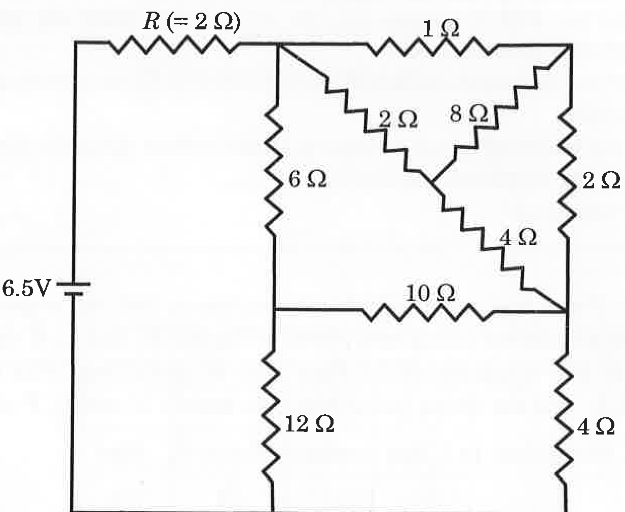
To find the current I flowing through the resistor R=2Ω, we analyze the given circuit by identifying and simplifying two nested Wheatstone bridge networks.
Step 1: Analysis of the First Wheatstone Bridge (Upper Right Sub-circuit)
Let us designate the following nodes in the upper-right sub-circuit:
- Node A: Junction immediately after resistor R.
- Node C: Top-right corner node.
- Node M: Central junction between the 2Ω, 8Ω, and 4Ω resistors.
- Node E: Junction connecting the upper bridge, the 10Ω resistor, and the lower-right 4Ω resistor.
The upper-right network between Node A and Node E consists of:
- RAC=1Ω
- RCE=2Ω
- RAM=2Ω
- RME=4Ω
- RMC=8Ω (connecting Nodes M and C)
Checking the ratio of resistances for the bridge:
RCERAC=2Ω1Ω=21
RMERAM=4Ω2Ω=21
Since RCERAC=RMERAM, the bridge is balanced. No current flows through the central branch containing RMC=8Ω, so this resistor can be removed.
The equivalent resistance between Node A and Node E (RAE) is calculated as:
RAE=(RAC+RCE)∥(RAM+RME)
RAE=(1+2)Ω∥(2+4)Ω=3Ω∥6Ω
RAE=3+63×6=918=2Ω
Step 2: Analysis of the Second Wheatstone Bridge (Main Network)
Now consider the remaining circuit between Node A and the ground reference line (Node G, 0 V):
- Node B: Junction between the 6Ω and 12Ω resistors.
- Resistor RAB=6Ω
- Resistor RBG=12Ω
- Resistor RAE=2Ω (simplified from Step 1)
- Resistor REG=4Ω
- Resistor RBE=10Ω (connecting Nodes B and E)
Checking the ratio of resistances for this second bridge:
RBGRAB=12Ω6Ω=21
REGRAE=4Ω2Ω=21
Since RBGRAB=REGRAE, this bridge is also balanced. Consequently, no current flows through the central 10Ω resistor, and it can be removed.
me equivalent resistance between Node A and Ground G (RAG) is:
RAG=(RAB+RBG)∥(RAE+REG)
RAG=(6+12)Ω∥(2+4)Ω=18Ω∥6Ω
RAG=18+618×6=24108=4.5Ω
Step 3: Calculation of Total Circuit Resistance and Current I
The total equivalent resistance Req connected across the 6.5 V battery consists of R=2Ω in series with RAG:
Req=R+RAG=2Ω+4.5Ω=6.5Ω
Using Ohm's Law, the current I flowing through resistor R is:
I=ReqV=6.5Ω6.5 V=1 A