JEE Challenger
More from Electromagnetic Induction

Work Done by Batteries Against Induced EMF in Coupled LR Circuits

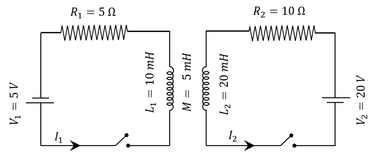
Two LRLR circuits have their inductors placed adjacent to one another as shown in the diagram. The values for self-inductances, resistances, mutual inductance, and applied voltages are given in the circuit diagram. Upon closing both switches simultaneously, find the total work done by the batteries against the induced EMF\text{EMF} in the inductors by the time steady-state current is reached (in mJ\text{mJ}).

Question Diagram 1
Official Numerical Answer55

Step-by-Step Solution

To find the total work done by the batteries against the induced EMF in the inductors, we analyze the system from the initial state (t=0t = 0) to the steady state (t→∞t \to \infty).

1. Steady-State Currents

In the steady state, the currents in both circuits become constant, meaning di1dt=0\frac{di_1}{dt} = 0 and di2dt=0\frac{di_2}{dt} = 0. Consequently, the induced EMFs drop to zero, and the steady-state currents are determined entirely by Ohm's Law:

I1=V1R1=5 V5 Ω=1 AI_1 = \frac{V_1}{R_1} = \frac{5\text{ V}}{5\ \Omega} = 1\text{ A}

I2=V2R2=20 V10 Ω=2 AI_2 = \frac{V_2}{R_2} = \frac{20\text{ V}}{10\ \Omega} = 2\text{ A}

2. Work Done Against Induced EMF

The induced EMFs in the two inductors are given by: e1=L1di1dt+Mdi2dte_1 = L_1 \frac{di_1}{dt} + M \frac{di_2}{dt} e2=L2di2dt+Mdi1dte_2 = L_2 \frac{di_2}{dt} + M \frac{di_1}{dt}

Here, the positive sign for the mutual inductance term MM is used because both currents enter the top terminals of their respective inductors (both flow downwards through L1L_1 and L2L_2), meaning their magnetic fluxes aid each other.

The rate at which work is done by the batteries specifically against these induced EMFs is: Pind=e1i1+e2i2P_{\text{ind}} = e_1 i_1 + e_2 i_2

Substituting e1e_1 and e2e_2: Pind=i1(L1di1dt+Mdi2dt)+i2(L2di2dt+Mdi1dt)P_{\text{ind}} = i_1 \left( L_1 \frac{di_1}{dt} + M \frac{di_2}{dt} \right) + i_2 \left( L_2 \frac{di_2}{dt} + M \frac{di_1}{dt} \right) Pind=L1i1di1dt+L2i2di2dt+M(i1di2dt+i2di1dt)P_{\text{ind}} = L_1 i_1 \frac{di_1}{dt} + L_2 i_2 \frac{di_2}{dt} + M \left( i_1 \frac{di_2}{dt} + i_2 \frac{di_1}{dt} \right) Pind=ddt(12L1i12+12L2i22+Mi1i2)P_{\text{ind}} = \frac{d}{dt} \left( \frac{1}{2} L_1 i_1^2 + \frac{1}{2} L_2 i_2^2 + M i_1 i_2 \right)

Integrating PindP_{\text{ind}} over time from t=0t = 0 (where i1=0,i2=0i_1 = 0, i_2 = 0) to the steady state (i1=I1,i2=I2i_1 = I_1, i_2 = I_2), the total work done WW against the induced EMFs equals the total magnetic energy stored in the coupled system:

W=∫0∞Pind dt=12L1I12+12L2I22+MI1I2W = \int_0^\infty P_{\text{ind}} \, dt = \frac{1}{2} L_1 I_1^2 + \frac{1}{2} L_2 I_2^2 + M I_1 I_2

3. Numerical Calculation

Given:

  • L1=10 mHL_1 = 10\text{ mH}
  • L2=20 mHL_2 = 20\text{ mH}
  • M=5 mHM = 5\text{ mH}
  • I1=1 AI_1 = 1\text{ A}
  • I2=2 AI_2 = 2\text{ A}

Substituting these values into the energy expression: W=(12×10×12)+(12×20×22)+(5×1×2) mJW = \left( \frac{1}{2} \times 10 \times 1^2 \right) + \left( \frac{1}{2} \times 20 \times 2^2 \right) + (5 \times 1 \times 2) \text{ mJ}

W=5+40+10=55 mJW = 5 + 40 + 10 = 55\text{ mJ}

The total work done by the batteries against the induced EMF is 55.