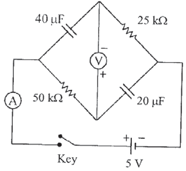
To determine which of the statements are correct, let us analyze the transient behavior of the given RC bridge circuit after the key is closed at time t=0.
1. Circuit Parameters and Setup
Let:
- The DC supply voltage be V=5 V.
- The potential at the right vertex (connected to the negative terminal of the battery) be VR=0 V.
- The potential at the left vertex (connected to the positive terminal of the battery through the ammeter) be VL=5 V.
- The top node potential be Vtop(t).
- The bottom node potential be Vbottom(t).
The voltmeter is connected with its positive terminal at the bottom node and negative terminal at the top node. Therefore, the reading displayed by the voltmeter is:
Vm(t)=Vbottom(t)−Vtop(t)
2. Time Constants of the Branches
-
Top Branch: Consists of capacitor C1=40 μF and resistor R1=25 kΩ.
τ1=R1C1=(25×103 Ω)×(40×10−6 F)=1 s
-
Bottom Branch: Consists of resistor R2=50 kΩ and capacitor C2=20 μF.
τ2=R2C2=(50×103 Ω)×(20×10−6 F)=1 s
3. Node Potentials as Functions of Time t
-
Top Node (Vtop(t)):
At t=0+, the uncharged capacitor C1 acts as a short circuit, so Vtop(0+)=VL=5 V.
At steady state (t→∞), C1 acts as an open circuit, so no current flows through R1, yielding Vtop(∞)=VR=0 V.
Thus,
Vtop(t)=5e−t/τ1=5e−t V
-
Bottom Node (Vbottom(t)):
At t=0+, the uncharged capacitor C2 acts as a short circuit, so Vbottom(0+)=VR=0 V.
At steady state (t→∞), C2 acts as an open circuit, so no current flows through R2, yielding Vbottom(∞)=VL=5 V.
Thus,
Vbottom(t)=5(1−e−t/τ2)=5(1−e−t) V
4. Evaluation of Options
Option A & Option B: Voltmeter Reading
The voltmeter reading at time t is:
Vm(t)=Vbottom(t)−Vtop(t)=5(1−e−t)−5e−t=5(1−2e−t) V
-
Just after the key is pressed (t=0+):
Vm(0+)=5(1−2)=−5 V
-
After a long time (t→∞):
Vm(∞)=5(1−0)=+5 V
Statement (A) is TRUE.
-
To find the time t when Vm(t)=0 V:
5(1−2e−t)=0⟹2e−t=1⟹et=2⟹t=ln2 seconds
Statement (B) is TRUE.
Option C & Option D: Ammeter Current
The total current supplied by the source and passing through the ammeter is I(t)=i1(t)+i2(t), where:
- i1(t) is the current in the top branch:
i1(t)=R1Vtop(t)−VR=25×1035e−t=0.2e−t mA
- i2(t) is the current in the bottom branch:
i2(t)=R2VL−Vbottom(t)=50×1035−5(1−e−t)=50×1035e−t=0.1e−t mA
The total current measured by the ammeter is:
I(t)=(0.2+0.1)e−t mA=0.3e−t mA
-
At t=0 s, I(0)=0.3 mA.
-
At t=1 s:
I(1)=0.3e−1 mA=eI(0)
Statement (C) is TRUE.
-
As t→∞:
I(∞)=limt→∞0.3e−t=0 A
Statement (D) is TRUE.
Conclusion
Statements A, B, C, and D are all correct.