Switching Circuit from AC Source to DC Battery with Capacitor
At time , terminal in the circuit shown in the diagram is connected to by a key, and an alternating current , with and starts flowing with the initial direction indicated in the figure. At time , the key is switched from to . From that instant onwards, only and remain connected. A total charge flows from the battery to fully charge the capacitor. If , , and the battery is an ideal source with an of , select the correct statement(s).
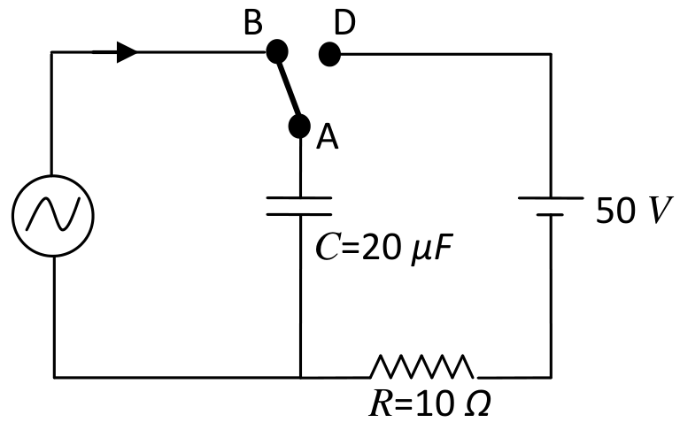
Options
The magnitude of the maximum charge on the capacitor before is .
The current in the left branch of the circuit just before is clockwise.
Immediately after terminal is connected to , the current flowing in resistor is .
.
Topics & Concepts
Step-by-Step Solution
To determine the correct statements, we analyze the circuit during each phase of the operation.
Phase 1: From to (A is connected to B)
During this time, the capacitor of capacitance is connected solely to the AC current source. The current supplied to the capacitor is given by: with and .
The arrow indicates that for , current flows clockwise in the left loop, which deposits positive charge on the upper plate of the capacitor. Assuming the capacitor is initially uncharged (), the charge on the upper plate of the capacitor at any time is:
-
Maximum charge on the capacitor: The maximum charge on the capacitor is: Therefore, statement (A) is incorrect.
-
Direction of current just before : The value of the current just before switching is: Since the current is negative, its direction is opposite to the initial reference direction (clockwise), which means the current is flowing counter-clockwise. Therefore, statement (B) is incorrect.
Phase 2: After (A is connected to D)
At the instant of switching ():
-
The charge on the upper plate of the capacitor is:
-
The potential difference across the capacitor plates (upper plate relative to the lower plate) is:
-
Current in resistor immediately after switching: When terminal is connected to , the capacitor is placed in series with the ideal battery and the resistor . Taking the lower plate of the capacitor as the reference potential ():
- The upper plate has potential , so terminal is at .
- The battery's positive terminal is connected to , meaning its negative terminal is at a potential of:
- The resistor is connected between the lower plate () and the negative terminal of the battery ().
Thus, the initial potential drop across the resistor is: The current flowing through immediately after the connection is: Therefore, statement (C) is correct.
-
Total charge flowing from the battery: In the final steady state, the capacitor is fully charged by the DC source, such that its upper plate is at a potential of relative to the lower plate:
The total charge that leaves the positive terminal of the battery to reach the upper plate of the capacitor is: Therefore, statement (D) is correct.
Conclusion:
The correct statements are (C) and (D).