Output Waveform Y for Given Logic Circuit and Input Waveforms
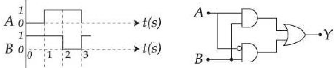
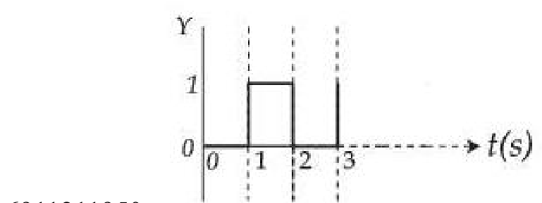
The output for the given inputs and to the circuit is :
Options
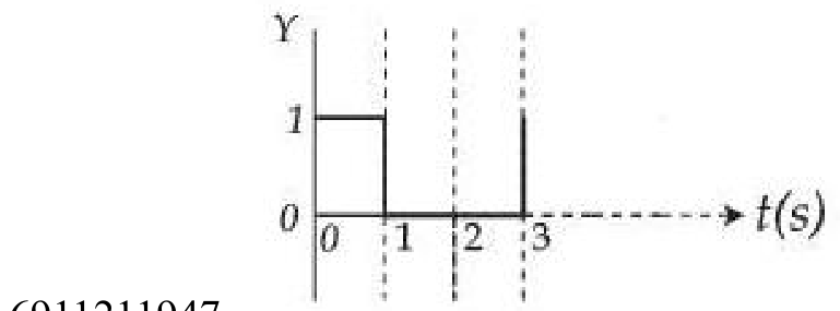
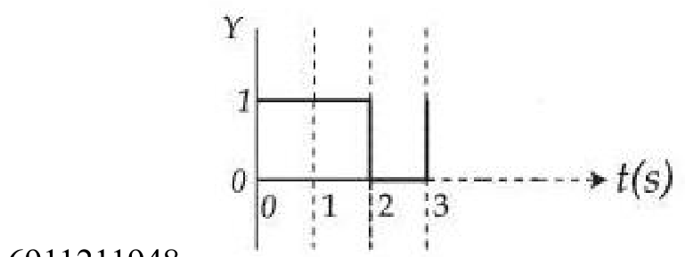
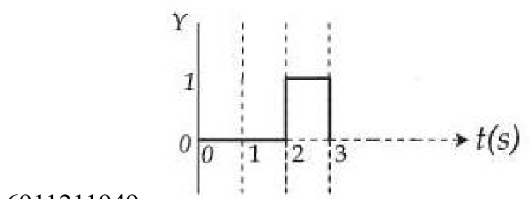
Topics & Concepts
Step-by-Step Solution
To determine the output waveform , we first analyze the given logic circuit and then evaluate its output for each time interval.
1. Analysis of the Logic Circuit
The logic circuit consists of two AND gates and one OR gate:
-
The upper AND gate receives input and the inverted input (indicated by the bubble at its lower input terminal). Hence, its output is:
-
The lower AND gate receives the inverted input (indicated by the bubble at its upper input terminal) and input . Hence, its output is:
-
The outputs and are fed into an OR gate to produce the final output :
Thus, the given circuit represents an XOR (Exclusive-OR) gate, which produces an output of when the inputs and are different, and when they are the same.
2. Time-Interval Analysis of Inputs and Output
From the given input waveforms of and :
-
For :
-
For :
-
For :
3. Conclusion
The output is at logic level for and at logic level for . This corresponds to the waveform depicted in Option B.