Maximum Current in Dual Inductor Circuit with Switches
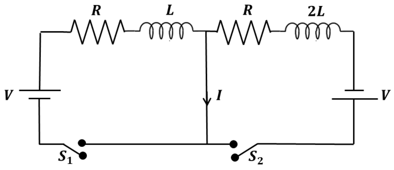
In the circuit depicted below, switches and are simultaneously shut at time , initiating current throughout the circuit. Each battery supplies an identical electromotive force (emf) with the polarities displayed. Assume mutual inductance between the two inductors is negligible. The electric current passing through the central branch attains its peak value at time . Which of the following statements is (are) correct?
Options
Topics & Concepts
Step-by-Step Solution
To determine the correct statements, we analyze the behavior of the circuit after the switches and are closed at .
1. Decoupling the Circuit into Two Independent Loops
The central wire has zero resistance and zero inductance, meaning it acts as an ideal conductor. Consequently, the potential difference across the central wire is zero:
Because of this, the circuit decouples into two independent circuits sharing the common middle branch:
- Left Loop: Consisting of the left battery of emf , switch , a resistor , an inductor , and the middle wire.
- Right Loop: Consisting of the right battery of emf , switch , a resistor , an inductor , and the middle wire.
2. Currents in the Two Loops
-
Left Loop: The left battery has its positive terminal at the top, driving a clockwise current . Through the middle wire, is directed downwards. Applying Kirchhoff's Voltage Law to the left loop: With the initial condition , solving this standard first-order differential equation yields:
-
Right Loop: The right battery has its positive terminal at the bottom, driving a clockwise current in the right loop. Through the middle wire, is directed upwards. Applying Kirchhoff's Voltage Law to the right loop: With the initial condition , the current is given by:
3. Net Current in the Central Wire
Taking the downward direction as positive, the net current through the central wire is:
4. Finding the Time of Maximum Current
To find the time at which reaches its maximum magnitude, we set :
Dividing both sides by :
Taking the natural logarithm of both sides:
This matches statement (D).
5. Calculating the Maximum Current
Substitute back into the expression for :
Thus:
This matches statement (B).
Conclusion
The correct statements are (B) and (D).