JEE Challenger
More from Alternating Current

Matching Parameters in Switched Inductor Capacitor Resistor Circuit

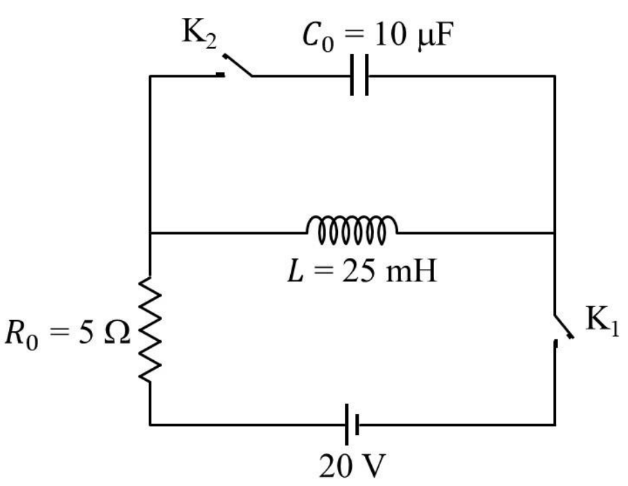
The circuit shown in the figure contains an inductor LL, a capacitor C0C_0, a resistor R0R_0 and an ideal battery. The circuit also contains two keys K1\text{K}_1 and K2\text{K}_2. Initially, both the keys are open and there is no charge on the capacitor. At an instant, key K1\text{K}_1 is closed and immediately after this the current in R0R_0 is found to be I1I_1. After a long time, the current attains a steady state value I2I_2. Thereafter, K2\text{K}_2 is closed and simultaneously K1\text{K}_1 is opened and the voltage across C0C_0 oscillates with amplitude V0V_0 and angular frequency ω0\omega_0.

Match the quantities mentioned in List-I with their values in List-II and choose the correct option.
List-IList-II(P) The value of I1 in Ampere is(1) 0(Q) The value of I2 in Ampere is(2) 2(R) The value of ω0 in kilo-radians/s is(3) 4(S) The value of V0 in Volt is(4) 20(5) 200\begin{array}{ll} \text{\textbf{List-I}} & \text{\textbf{List-II}} \\ \text{(P) The value of } I_1 \text{ in Ampere is} & \text{(1) } 0 \\ \text{(Q) The value of } I_2 \text{ in Ampere is} & \text{(2) } 2 \\ \text{(R) The value of } \omega_0 \text{ in kilo-radians/s is} & \text{(3) } 4 \\ \text{(S) The value of } V_0 \text{ in Volt is} & \text{(4) } 20 \\ & \text{(5) } 200 \end{array}
Question Diagram 1

Options

A

P1;Q3;R2;S5\text{P} \rightarrow 1; \text{Q} \rightarrow 3; \text{R} \rightarrow 2; \text{S} \rightarrow 5

Correct
B

P1;Q2;R3;S5\text{P} \rightarrow 1; \text{Q} \rightarrow 2; \text{R} \rightarrow 3; \text{S} \rightarrow 5

C

P1;Q3;R2;S4\text{P} \rightarrow 1; \text{Q} \rightarrow 3; \text{R} \rightarrow 2; \text{S} \rightarrow 4

D

P2;Q5;R3;S4\text{P} \rightarrow 2; \text{Q} \rightarrow 5; \text{R} \rightarrow 3; \text{S} \rightarrow 4

Step-by-Step Solution

To determine the correct matching between List-I and List-II, we analyze the behavior of the circuit in the given sequence of events:


1. Immediately after closing key K1\text{K}_1 (K2\text{K}_2 open)

When key K1\text{K}_1 is closed while K2\text{K}_2 remains open, the active loop consists of the battery (E=20 VE = 20\text{ V}), the resistor (R0=5 ΩR_0 = 5\ \Omega), and the inductor (L=25 mHL = 25\text{ mH}) connected in series.

Since the current through an inductor cannot change instantaneously: I1=IL(0+)=IL(0)=0 AI_1 = I_L(0^+) = I_L(0^-) = 0\text{ A}

Thus: P1\text{P} \rightarrow 1


2. Steady State after a long time

After a long time, the inductor behaves as a pure conducting wire (short circuit with zero resistance). The steady-state current I2I_2 in the circuit is solely determined by the battery voltage and the resistor R0R_0:

I2=ER0=20 V5 Ω=4 AI_2 = \frac{E}{R_0} = \frac{20\text{ V}}{5\ \Omega} = 4\text{ A}

Thus: Q3\text{Q} \rightarrow 3


3. Closing key K2\text{K}_2 and opening key K1\text{K}_1

When K1\text{K}_1 is opened and K2\text{K}_2 is closed simultaneously, the battery and resistor R0R_0 are disconnected from the loop. The circuit reduces to a pure LCLC circuit consisting of the inductor LL and capacitor C0C_0.

(i) Angular Frequency of Oscillation (ω0\omega_0)

The natural angular frequency of the LCLC circuit is given by:

ω0=1LC0\omega_0 = \frac{1}{\sqrt{L C_0}}

Substituting the given values (L=25 mH=25×103 HL = 25\text{ mH} = 25 \times 10^{-3}\text{ H} and C0=10 μF=10×106 FC_0 = 10\ \mu\text{F} = 10 \times 10^{-6}\text{ F}):

ω0=1(25×103 H)×(10×106 F)=125×108=15×104=2000 rad/s=2 krad/s\omega_0 = \frac{1}{\sqrt{(25 \times 10^{-3}\text{ H}) \times (10 \times 10^{-6}\text{ F})}} = \frac{1}{\sqrt{25 \times 10^{-8}}} = \frac{1}{5 \times 10^{-4}} = 2000\text{ rad/s} = 2\text{ krad/s}

Thus: R2\text{R} \rightarrow 2

(ii) Voltage Amplitude across the Capacitor (V0V_0)

At the instant K1\text{K}_1 is opened, the current through the inductor is I2=4 AI_2 = 4\text{ A}, and the initial charge on the capacitor is zero. By conservation of energy, the maximum magnetic energy stored in the inductor equals the maximum electrostatic energy stored in the capacitor:

12LI22=12C0V02\frac{1}{2} L I_2^2 = \frac{1}{2} C_0 V_0^2

Solving for V0V_0:

V0=I2LC0=4×25×10310×106=4×2500=4×50=200 VV_0 = I_2 \sqrt{\frac{L}{C_0}} = 4 \times \sqrt{\frac{25 \times 10^{-3}}{10 \times 10^{-6}}} = 4 \times \sqrt{2500} = 4 \times 50 = 200\text{ V}

Thus: S5\text{S} \rightarrow 5


Summary of Matching:

  • P1\text{P} \rightarrow 1
  • Q3\text{Q} \rightarrow 3
  • R2\text{R} \rightarrow 2
  • S5\text{S} \rightarrow 5

This corresponds to Option A.

Matching Parameters in Switched Inductor Capacitor Resistor Circuit | Physics PYQ Solution - JEE Challenger