Induced EMF in Equilateral Triangular Loop Entering Magnetic Field
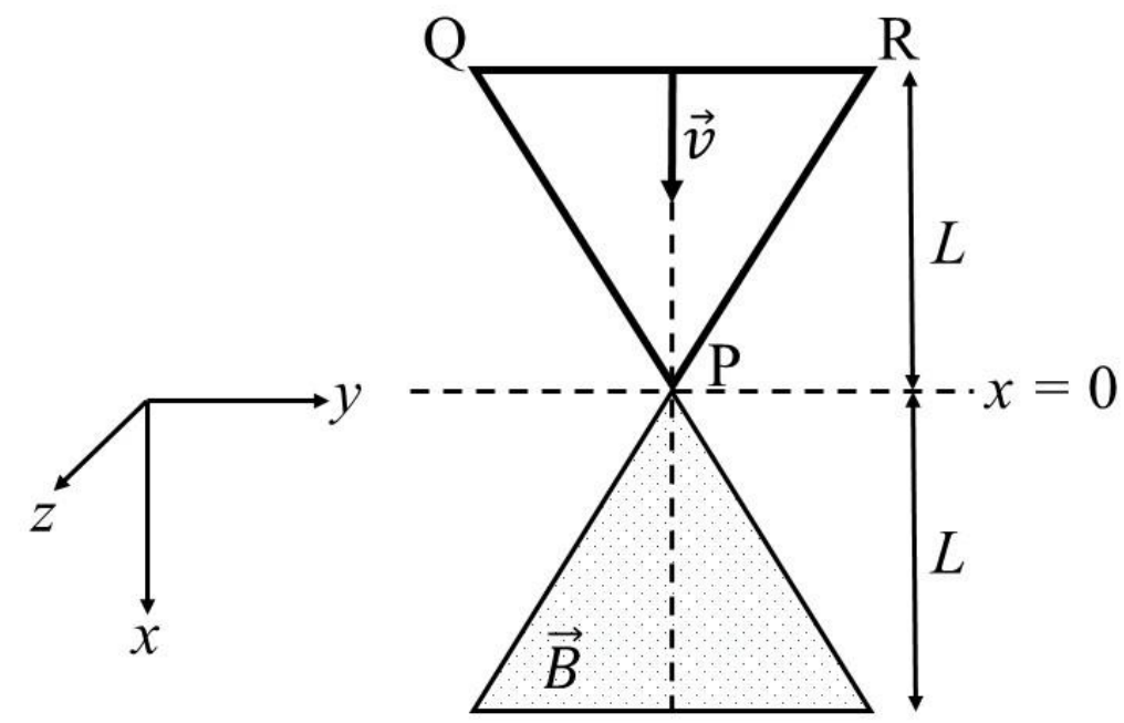
A region in the form of an equilateral triangle (in - plane) of height has a uniform magnetic field pointing in the -direction. A conducting loop PQR, in the form of an equilateral triangle of the same height , is placed in the - plane with its vertex P at in the orientation shown in the figure. At , the loop starts entering the region of the magnetic field with a uniform velocity along the -direction. The plane of the loop and its orientation remain unchanged throughout its motion.
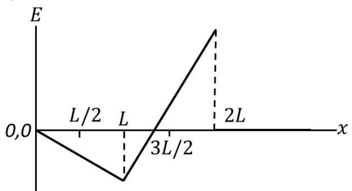
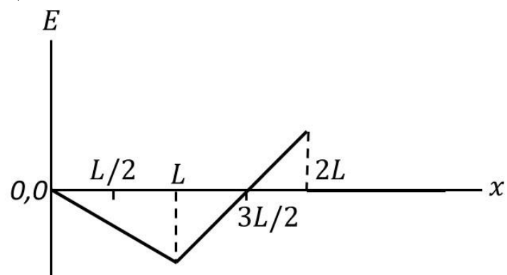
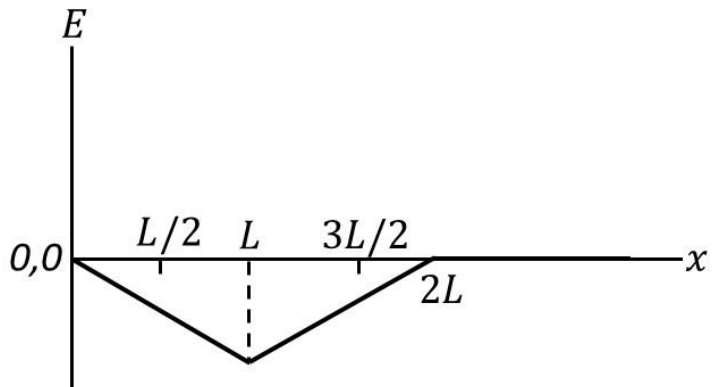
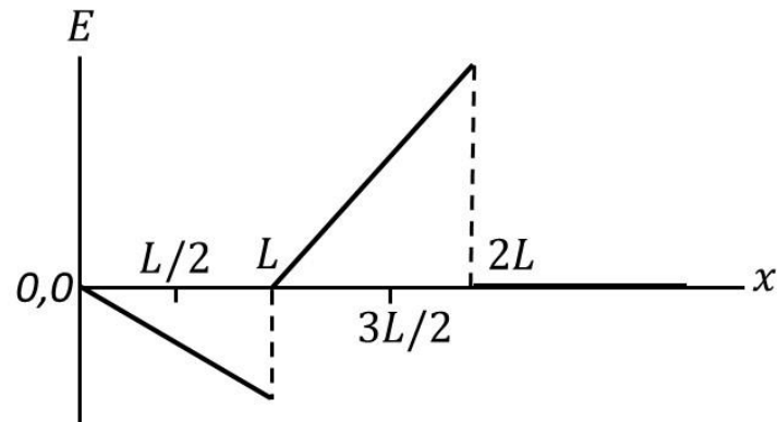
Which of the following graph best depicts the variation of the induced emf () in the loop as a function of the distance () starting from ?
Options
Topics & Concepts
Step-by-Step Solution
To determine the variation of the induced electromotive force (emf), , as a function of the position of the loop, we analyze the magnetic flux linked with the conducting loop as it enters and leaves the triangular magnetic field region.
1. Geometry and Coordinate Setup
-
Magnetic Field Region: An equilateral triangle of height located in .
- The vertex of the field region is at .
- The base of the field region is at .
- The width of the magnetic field region at any coordinate is:
-
Conducting Loop (PQR): An equilateral triangle of height moving in the -direction with velocity .
- At , vertex P is at .
- At position , the loop occupies the spatial interval .
- The width of the loop at any coordinate is:
2. Derivation of Overlap Area and Induced EMF
By Faraday's law of electromagnetic induction, the induced emf is given by:
Phase 1: (Loop entering the field)
The field region and the loop overlap in . The overlapping width at is .
Equating yields:
Thus, the area of overlap is:
Taking the derivative with respect to :
Therefore, the induced emf in this interval is:
- At :
- At :
Phase 2: (Loop leaving the field)
The field region () and the loop () overlap in . Since , the point lies within the interval .
The total area of overlap is:
Evaluating the integrals:
Taking the derivative with respect to :
Therefore, the induced emf in this interval is:
- At :
- At :
- At :
3. Conclusion and Comparison with Options
- For , decreases linearly from to .
- For , increases linearly, crossing zero at , and reaches a positive maximum at with magnitude twice that at .
This behavior is correctly depicted in Option (A).