Identification of Circuit Components Between Points X and Y
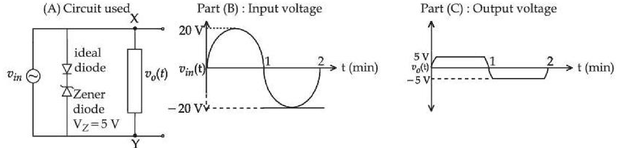
For the given circuit (shown in part (A)) the time dependent input voltage and corresponding output are shown in part (B) and part (C), respectively. Identify the components that are used in the circuit between points X and Y.
Options




Topics & Concepts
Step-by-Step Solution
To determine the correct combination of components placed between points and , let us analyze the operation of the circuit during both positive and negative half-cycles of the input voltage .
1. Analysis of the Output Waveform
- The input voltage is a sinusoidal wave with a peak amplitude of .
- The output voltage is clipped at:
- during the positive half-cycle ().
- during the negative half-cycle ().
2. Analysis of the Middle Branch in Part (A)
The middle branch connected in parallel with the source consists of:
-
An ideal diode pointing downwards (anode connected to , cathode connected to the Zener diode).
-
A Zener diode () pointing upwards (cathode connected to the ideal diode, anode connected to ).
-
For ():
- The ideal diode is forward biased (acts as a short circuit with zero voltage drop).
- The Zener diode is reverse biased. When , it undergoes Zener breakdown.
- This clamps the voltage across the parallel combination to .
-
For ():
- The ideal diode in the middle branch is reverse biased (acts as an open circuit).
- Thus, no current flows through the middle branch during the negative half-cycle.
3. Determination of the Components Between and
Since the middle branch is inactive during the negative half-cycle (), the circuit between points and must be responsible for clipping the output voltage at .
To achieve this:
- For (): The branch between and must act as an open circuit so that it does not interfere with the positive clipping provided by the middle branch.
- For (): The branch between and must conduct and undergo Zener breakdown at , clamping (or ).
This requirement is met by a series combination of:
- An ideal diode pointing towards (cathode at , anode towards ), which is reverse biased when and forward biased when .
- A Zener diode () pointing towards (anode towards , cathode at ), which is reverse biased and breaks down at when .
This configuration matches Option (B).
Conclusion
The correct component configuration between and is given by Option B.