JEE Challenger
More from Electric Charges and Fields

Electric Field and Potential Difference in Thin Charged Sheets Configurations

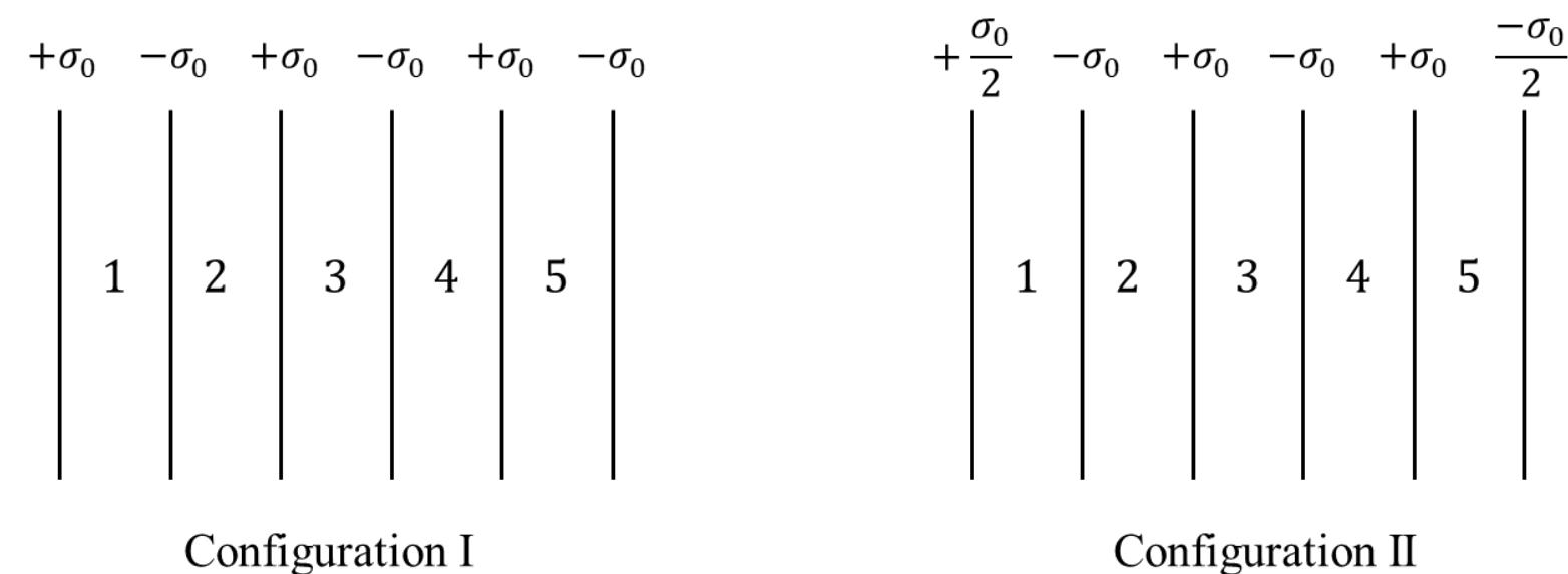
Six infinitely large and thin non-conducting sheets are fixed in configurations I and II. As shown in the figure, the sheets carry uniform surface charge densities which are indicated in terms of σ0\sigma_0. The separation between any two consecutive sheets is 1 μm1\text{ }\mu\text{m}. The various regions between the sheets are denoted as 1,2,3,41, 2, 3, 4 and 55. If σ0=9 μC/m2\sigma_0 = 9\text{ }\mu\text{C/m}^2, then which of the following statements is/are correct:

(Take permittivity of free space ϵ0=9×10¹² F/m\epsilon_0 = 9 \times 10^{-12}\text{ F/m})

Question Diagram 1

Options

A

In region 4 of the configuration I, the magnitude of the electric field is zero.

Correct
B

In region 3 of the configuration II, the magnitude of the electric field is σ0ϵ0\frac{\sigma_0}{\epsilon_0}.

C

Potential difference between the first and the last sheets of the configuration I is 5 V5\text{ V}.

D

Potential difference between the first and the last sheets of the configuration II is zero.

Step-by-Step Solution

To determine the correct statement(s), we analyze the electric field in each region for both configurations using the principle of superposition.

For a thin, infinitely large non-conducting sheet carrying a uniform surface charge density σ\sigma, the electric field produced at any point is: E=σ2ϵ0E = \frac{\sigma}{2\epsilon_0} directed away from a positively charged sheet and towards a negatively charged sheet.

If a region has a total surface charge density QLQ_L on all sheets to its left and QRQ_R on all sheets to its right, the net electric field (taking the rightward direction as positive, +i^+\hat{i}) in that region is given by: E=QLQR2ϵ0E = \frac{Q_L - Q_R}{2\epsilon_0}

Given data:

  • σ0=9 μC/m2=9×106 C/m2\sigma_0 = 9\text{ }\mu\text{C/m}^2 = 9 \times 10^{-6}\text{ C/m}^2
  • ϵ0=9×10¹² F/m\epsilon_0 = 9 \times 10^{-12}\text{ F/m}
  • Distance between consecutive sheets d=1 μm=106 md = 1\text{ }\mu\text{m} = 10^{-6}\text{ m}

The fundamental potential factor σ0dϵ0\frac{\sigma_0 d}{\epsilon_0} is: σ0dϵ0=(9×10⁶ C/m2)(106 m)9×10¹² F/m=1 V\frac{\sigma_0 d}{\epsilon_0} = \frac{(9 \times 10^{-6}\text{ C/m}^2)(10^{-6}\text{ m})}{9 \times 10^{-12}\text{ F/m}} = 1\text{ V}


1. Analysis of Configuration I

The surface charge densities on the six sheets from left to right are: σ1=+σ0,σ2=σ0,σ3=+σ0,σ4=σ0,σ5=+σ0,σ6=σ0\sigma_1 = +\sigma_0, \quad \sigma_2 = -\sigma_0, \quad \sigma_3 = +\sigma_0, \quad \sigma_4 = -\sigma_0, \quad \sigma_5 = +\sigma_0, \quad \sigma_6 = -\sigma_0

Let us calculate the net electric field in each region:

  • Region 1: QL=+σ0,QR=(σ0+σ0σ0+σ0σ0)=σ0Q_L = +\sigma_0, \quad Q_R = (-\sigma_0 + \sigma_0 - \sigma_0 + \sigma_0 - \sigma_0) = -\sigma_0 EI,1=σ0(σ0)2ϵ0=σ0ϵ0E_{\text{I}, 1} = \frac{\sigma_0 - (-\sigma_0)}{2\epsilon_0} = \frac{\sigma_0}{\epsilon_0}

  • Region 2: QL=σ0σ0=0,QR=σ0σ0+σ0σ0=0Q_L = \sigma_0 - \sigma_0 = 0, \quad Q_R = \sigma_0 - \sigma_0 + \sigma_0 - \sigma_0 = 0 EI,2=0E_{\text{I}, 2} = 0

  • Region 3: QL=σ0σ0+σ0=σ0,QR=σ0+σ0σ0=σ0Q_L = \sigma_0 - \sigma_0 + \sigma_0 = \sigma_0, \quad Q_R = -\sigma_0 + \sigma_0 - \sigma_0 = -\sigma_0 EI,3=σ0(σ0)2ϵ0=σ0ϵ0E_{\text{I}, 3} = \frac{\sigma_0 - (-\sigma_0)}{2\epsilon_0} = \frac{\sigma_0}{\epsilon_0}

  • Region 4: QL=σ0σ0+σ0σ0=0,QR=σ0σ0=0Q_L = \sigma_0 - \sigma_0 + \sigma_0 - \sigma_0 = 0, \quad Q_R = \sigma_0 - \sigma_0 = 0 EI,4=0E_{\text{I}, 4} = 0

  • Region 5: QL=σ0,QR=σ0Q_L = \sigma_0, \quad Q_R = -\sigma_0 EI,5=σ0ϵ0E_{\text{I}, 5} = \frac{\sigma_0}{\epsilon_0}

Evaluating Options for Configuration I:

  • Statement A: In region 4 of Configuration I, the electric field magnitude is EI,4=0E_{\text{I}, 4} = 0. (Statement A is CORRECT)

  • Statement C: Potential difference between the first and the last sheet of Configuration I is: ΔV=V1V6=k=15EI,kd=(σ0ϵ0+0+σ0ϵ0+0+σ0ϵ0)d=3σ0dϵ0=3×1 V=3 V\Delta V = V_1 - V_6 = \sum_{k=1}^{5} E_{\text{I}, k} \cdot d = \left(\frac{\sigma_0}{\epsilon_0} + 0 + \frac{\sigma_0}{\epsilon_0} + 0 + \frac{\sigma_0}{\epsilon_0}\right) d = \frac{3\sigma_0 d}{\epsilon_0} = 3 \times 1\text{ V} = 3\text{ V} (Statement C is INCORRECT)


2. Analysis of Configuration II

The surface charge densities on the six sheets from left to right are: σ1=+σ02,σ2=σ0,σ3=+σ0,σ4=σ0,σ5=+σ0,σ6=σ02\sigma_1 = +\frac{\sigma_0}{2}, \quad \sigma_2 = -\sigma_0, \quad \sigma_3 = +\sigma_0, \quad \sigma_4 = -\sigma_0, \quad \sigma_5 = +\sigma_0, \quad \sigma_6 = -\frac{\sigma_0}{2}

Let us calculate the net electric field in each region:

  • Region 1: QL=+σ02,QR=σ02    EII,1=σ02ϵ0Q_L = +\frac{\sigma_0}{2}, \quad Q_R = -\frac{\sigma_0}{2} \implies E_{\text{II}, 1} = \frac{\sigma_0}{2\epsilon_0}

  • Region 2: QL=σ02,QR=+σ02    EII,2=σ02ϵ0Q_L = -\frac{\sigma_0}{2}, \quad Q_R = +\frac{\sigma_0}{2} \implies E_{\text{II}, 2} = -\frac{\sigma_0}{2\epsilon_0}

  • Region 3: QL=+σ02,QR=σ02    EII,3=σ02ϵ0Q_L = +\frac{\sigma_0}{2}, \quad Q_R = -\frac{\sigma_0}{2} \implies E_{\text{II}, 3} = \frac{\sigma_0}{2\epsilon_0}

  • Region 4: QL=σ02,QR=+σ02    EII,4=σ02ϵ0Q_L = -\frac{\sigma_0}{2}, \quad Q_R = +\frac{\sigma_0}{2} \implies E_{\text{II}, 4} = -\frac{\sigma_0}{2\epsilon_0}

  • Region 5: QL=+σ02,QR=σ02    EII,5=σ02ϵ0Q_L = +\frac{\sigma_0}{2}, \quad Q_R = -\frac{\sigma_0}{2} \implies E_{\text{II}, 5} = \frac{\sigma_0}{2\epsilon_0}

Evaluating Options for Configuration II:

  • Statement B: In region 3 of Configuration II, the electric field magnitude is EII,3=σ02ϵ0|E_{\text{II}, 3}| = \frac{\sigma_0}{2\epsilon_0}. Statement B claims it is σ0ϵ0\frac{\sigma_0}{\epsilon_0}. (Statement B is INCORRECT)

  • Statement D: Potential difference between the first and the last sheet of Configuration II is: ΔV=V1V6=k=15EII,kd=(σ02ϵ0σ02ϵ0+σ02ϵ0σ02ϵ0+σ02ϵ0)d=σ0d2ϵ0=0.5 V0\Delta V = V_1 - V_6 = \sum_{k=1}^{5} E_{\text{II}, k} \cdot d = \left( \frac{\sigma_0}{2\epsilon_0} - \frac{\sigma_0}{2\epsilon_0} + \frac{\sigma_0}{2\epsilon_0} - \frac{\sigma_0}{2\epsilon_0} + \frac{\sigma_0}{2\epsilon_0} \right) d = \frac{\sigma_0 d}{2\epsilon_0} = 0.5\text{ V} \neq 0 (Statement D is INCORRECT)


Conclusion

Only statement A is correct.
Electric Field and Potential Difference in Thin Charged Sheets Configurations | Physics PYQ Solution - JEE Challenger