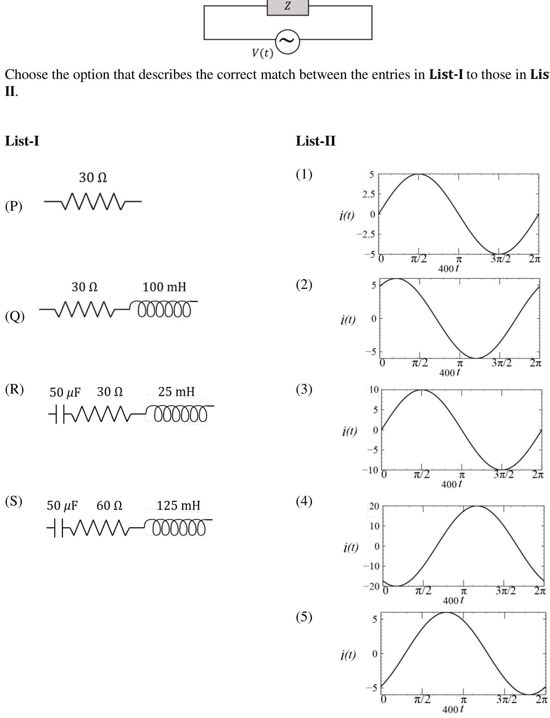
To find the correct match between the electrical loads in List-I and the current functions i ( t ) i(t) i ( t ) V ( t ) = 300 sin ( 400 t ) V V(t) = 300 \sin(400t)\text{ V} V ( t ) = 300 sin ( 400 t ) V
From the source voltage equation:
Peak voltage, V 0 = 300 V V_0 = 300\text{ V} V 0 = 300 V
Angular frequency, ω = 400 rad/s \omega = 400\text{ rad/s} ω = 400 rad/s
The current as a function of time is given by:
i ( t ) = I 0 sin ( 400 t − ϕ ) i(t) = I_0 \sin(400t - \phi) i ( t ) = I 0 sin ( 400 t − ϕ )
I 0 = V 0 Z I_0 = \frac{V_0}{Z} I 0 = Z V 0 Z = R 2 + ( X L − X C ) 2 Z = \sqrt{R^2 + (X_L - X_C)^2} Z = R 2 + ( X L − X C ) 2 ϕ = arctan ( X L − X C R ) \phi = \arctan\left(\frac{X_L - X_C}{R}\right) ϕ = arctan ( R X L − X C )
Analysis of Load (P):
R = 30 Ω R = 30\ \Omega R = 30 Ω L = 0 L = 0 L = 0 C = 0 C = 0 C = 0 Impedance:
Z = R = 30 Ω Z = R = 30\ \Omega Z = R = 30 Ω
Peak current:
I 0 = 300 30 = 10 A I_0 = \frac{300}{30} = 10\text{ A} I 0 = 30 300 = 10 A
Phase angle:
ϕ = 0 \phi = 0 ϕ = 0
Current equation:
i ( t ) = 10 sin ( 400 t ) A i(t) = 10 \sin(400t)\text{ A} i ( t ) = 10 sin ( 400 t ) A
Looking at List-II:
Graph (3) has zero value at 400 t = 0 , π , 2 π 400t = 0, \pi, 2\pi 400 t = 0 , π , 2 π + 10 A +10\text{ A} + 10 A 400 t = π / 2 400t = \pi/2 400 t = π /2 − 10 A -10\text{ A} − 10 A 400 t = 3 π / 2 400t = 3\pi/2 400 t = 3 π /2
Thus, P → \rightarrow → .
Analysis of Load (Q):
R = 30 Ω R = 30\ \Omega R = 30 Ω L = 100 mH = 0.1 H L = 100\text{ mH} = 0.1\text{ H} L = 100 mH = 0.1 H Inductive reactance:
X L = ω L = 400 × 0.1 = 40 Ω X_L = \omega L = 400 \times 0.1 = 40\ \Omega X L = ω L = 400 × 0.1 = 40 Ω
Impedance:
Z = R 2 + X L 2 = 30 2 + 40 2 = 50 Ω Z = \sqrt{R^2 + X_L^2} = \sqrt{30^2 + 40^2} = 50\ \Omega Z = R 2 + X L 2 = 3 0 2 + 4 0 2 = 50 Ω
Peak current:
I 0 = 300 50 = 6 A I_0 = \frac{300}{50} = 6\text{ A} I 0 = 50 300 = 6 A
Phase angle:
tan ϕ = X L R = 40 30 = 4 3 ⟹ ϕ = arctan ( 4 3 ) ≈ 53 ∘ \tan\phi = \frac{X_L}{R} = \frac{40}{30} = \frac{4}{3} \implies \phi = \arctan\left(\frac{4}{3}\right) \approx 53^\circ tan ϕ = R X L = 30 40 = 3 4 ⟹ ϕ = arctan ( 3 4 ) ≈ 5 3 ∘
Current equation:
i ( t ) = 6 sin ( 400 t − 53 ∘ ) A i(t) = 6 \sin(400t - 53^\circ)\text{ A} i ( t ) = 6 sin ( 400 t − 5 3 ∘ ) A
Key characteristics of this wave:
At 400 t = 0 400t = 0 400 t = 0 i ( 0 ) = 6 sin ( − 53 ∘ ) ≈ − 4.8 A i(0) = 6 \sin(-53^\circ) \approx -4.8\text{ A} i ( 0 ) = 6 sin ( − 5 3 ∘ ) ≈ − 4.8 A
Zero crossing occurs when 400 t = 53 ∘ ≈ 0.93 rad 400t = 53^\circ \approx 0.93\text{ rad} 400 t = 5 3 ∘ ≈ 0.93 rad 0 0 0 π / 2 \pi/2 π /2
Peak of + 6 A +6\text{ A} + 6 A 400 t = 90 ∘ + 53 ∘ = 143 ∘ 400t = 90^\circ + 53^\circ = 143^\circ 400 t = 9 0 ∘ + 5 3 ∘ = 14 3 ∘ π / 2 \pi/2 π /2 π \pi π
Looking at List-II:
Graph (5) starts below zero at 400 t = 0 400t = 0 400 t = 0 π / 2 \pi/2 π /2 π / 2 \pi/2 π /2 π \pi π
Thus, Q → \rightarrow → .
Analysis of Load (R):
C = 50 μ F = 50 × 10 − 6 F C = 50\ \mu\text{F} = 50 \times 10^{-6}\text{ F} C = 50 μ F = 50 × 1 0 − 6 F R = 30 Ω R = 30\ \Omega R = 30 Ω L = 25 mH = 25 × 10 − 3 H L = 25\text{ mH} = 25 \times 10^{-3}\text{ H} L = 25 mH = 25 × 1 0 − 3 H Reactances:
X C = 1 ω C = 1 400 × 50 × 10 − 6 = 50 Ω X_C = \frac{1}{\omega C} = \frac{1}{400 \times 50 \times 10^{-6}} = 50\ \Omega X C = ω C 1 = 400 × 50 × 1 0 − 6 1 = 50 Ω X L = ω L = 400 × 25 × 10 − 3 = 10 Ω X_L = \omega L = 400 \times 25 \times 10^{-3} = 10\ \Omega X L = ω L = 400 × 25 × 1 0 − 3 = 10 Ω
Net reactance:
X = X L − X C = 10 − 50 = − 40 Ω X = X_L - X_C = 10 - 50 = -40\ \Omega X = X L − X C = 10 − 50 = − 40 Ω
Impedance:
Z = R 2 + X 2 = 30 2 + ( − 40 ) 2 = 50 Ω Z = \sqrt{R^2 + X^2} = \sqrt{30^2 + (-40)^2} = 50\ \Omega Z = R 2 + X 2 = 3 0 2 + ( − 40 ) 2 = 50 Ω
Peak current:
I 0 = 300 50 = 6 A I_0 = \frac{300}{50} = 6\text{ A} I 0 = 50 300 = 6 A
Phase angle:
tan ϕ = − 40 30 = − 4 3 ⟹ ϕ = − 53 ∘ \tan\phi = \frac{-40}{30} = -\frac{4}{3} \implies \phi = -53^\circ tan ϕ = 30 − 40 = − 3 4 ⟹ ϕ = − 5 3 ∘
Current equation:
i ( t ) = 6 sin ( 400 t + 53 ∘ ) A i(t) = 6 \sin(400t + 53^\circ)\text{ A} i ( t ) = 6 sin ( 400 t + 5 3 ∘ ) A
Key characteristics of this wave:
At 400 t = 0 400t = 0 400 t = 0 i ( 0 ) = 6 sin ( 53 ∘ ) ≈ + 4.8 A i(0) = 6 \sin(53^\circ) \approx +4.8\text{ A} i ( 0 ) = 6 sin ( 5 3 ∘ ) ≈ + 4.8 A
Peak of + 6 A +6\text{ A} + 6 A 400 t = 90 ∘ − 53 ∘ = 37 ∘ 400t = 90^\circ - 53^\circ = 37^\circ 400 t = 9 0 ∘ − 5 3 ∘ = 3 7 ∘ π / 2 \pi/2 π /2
Looking at List-II:
Graph (2) starts near + 5 A +5\text{ A} + 5 A 400 t = 0 400t = 0 400 t = 0 π / 2 \pi/2 π /2
Thus, R → \rightarrow → .
Analysis of Load (S):
C = 50 μ F C = 50\ \mu\text{F} C = 50 μ F R = 60 Ω R = 60\ \Omega R = 60 Ω L = 125 mH = 0.125 H L = 125\text{ mH} = 0.125\text{ H} L = 125 mH = 0.125 H Reactances:
X C = 50 Ω X_C = 50\ \Omega X C = 50 Ω X L = ω L = 400 × 0.125 = 50 Ω X_L = \omega L = 400 \times 0.125 = 50\ \Omega X L = ω L = 400 × 0.125 = 50 Ω
Net reactance:
X = X L − X C = 50 − 50 = 0 Ω (Resonance) X = X_L - X_C = 50 - 50 = 0\ \Omega\ \text{(Resonance)} X = X L − X C = 50 − 50 = 0 Ω (Resonance)
Impedance:
Z = R = 60 Ω Z = R = 60\ \Omega Z = R = 60 Ω
Peak current:
I 0 = 300 60 = 5 A I_0 = \frac{300}{60} = 5\text{ A} I 0 = 60 300 = 5 A
Phase angle:
ϕ = 0 \phi = 0 ϕ = 0
Current equation:
i ( t ) = 5 sin ( 400 t ) A i(t) = 5 \sin(400t)\text{ A} i ( t ) = 5 sin ( 400 t ) A
Looking at List-II:
Graph (1) is a sine wave with amplitude 5 A 5\text{ A} 5 A
Thus, S → \rightarrow → .
Final Matching: P → 3 , Q → 5 , R → 2 , S → 1 \text{P}\rightarrow 3, \quad \text{Q}\rightarrow 5, \quad \text{R}\rightarrow 2, \quad \text{S}\rightarrow 1 P → 3 , Q → 5 , R → 2 , S → 1
This corresponds to option (A) .