JEE Challenger
More from Electrostatic Potential and Capacitance

Charge Flow Through Switch in RC Bridge Circuit

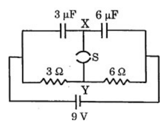
A circuit is connected as shown in the figure with the switch S\mathrm{S} open.

Diagram 0

When the switch is closed, the total amount of charge that flows from Y\mathrm{Y} to X\mathrm{X} is

Options

A

00

B

54 μC54\text{ }\mu\text{C}

C

27 μC27\text{ }\mu\text{C}

Correct
D

81 μC81\text{ }\mu\text{C}

Step-by-Step Solution

To determine the total amount of charge that flows from Y\mathrm{Y} to X\mathrm{X} when the switch S\mathrm{S} is closed, we analyze the circuit before and after the switch is closed.

1. Initial State (Switch S\mathrm{S} is open)

Let the negative terminal of the 9 V9\text{ V} battery be at a reference potential of 0 V0\text{ V} and the positive terminal be at 9 V9\text{ V}.

  • The potential of the left wire is Vleft=9 VV_{\text{left}} = 9\text{ V}.
  • The potential of the right wire is Vright=0 VV_{\text{right}} = 0\text{ V}.

Before the switch is closed, the two capacitors C1=3 μFC_1 = 3\text{ }\mu\text{F} and C2=6 μFC_2 = 6\text{ }\mu\text{F} are connected in series.
Since node X\mathrm{X} was isolated:

  • The right plate of C1C_1 and the left plate of C2C_2 are connected together at node X\mathrm{X}.
  • The net initial charge at node X\mathrm{X} is:
    qX,initial=0 μCq_{X, \text{initial}} = 0\text{ }\mu\text{C}

2. Final State (Switch S\mathrm{S} is closed)

In the steady state after closing the switch, no current flows into or out of the capacitors. A steady current flows only through the resistive branch:
I=VR1+R2=9 V3 Ω+6 Ω=1 AI = \frac{V}{R_1 + R_2} = \frac{9\text{ V}}{3\text{ }\Omega + 6\text{ }\Omega} = 1\text{ A}

The potential at junction Y\mathrm{Y} is:
VY=Vleft−IR1=9 V−(1 A)(3 Ω)=6 VV_{\mathrm{Y}} = V_{\text{left}} - I R_1 = 9\text{ V} - (1\text{ A})(3\text{ }\Omega) = 6\text{ V}

Since switch S\mathrm{S} is closed, nodes X\mathrm{X} and Y\mathrm{Y} are at the same electric potential:
VX=VY=6 VV_{\mathrm{X}} = V_{\mathrm{Y}} = 6\text{ V}

Now, we calculate the charge on the plates connected to node X\mathrm{X}:

  • For capacitor C1=3 μFC_1 = 3\text{ }\mu\text{F}:
    The potential difference across it is Vleft−VX=9 V−6 V=3 VV_{\text{left}} - V_{\mathrm{X}} = 9\text{ V} - 6\text{ V} = 3\text{ V}.
    The charge on its right plate (connected to X\mathrm{X}) is:
    q1,right=−C1(Vleft−VX)=−3 μF×3 V=−9 μCq_{1, \text{right}} = -C_1(V_{\text{left}} - V_{\mathrm{X}}) = -3\text{ }\mu\text{F} \times 3\text{ V} = -9\text{ }\mu\text{C}

  • For capacitor C2=6 μFC_2 = 6\text{ }\mu\text{F}:
    The potential difference across it is VX−Vright=6 V−0 V=6 VV_{\mathrm{X}} - V_{\text{right}} = 6\text{ V} - 0\text{ V} = 6\text{ V}.
    The charge on its left plate (connected to X\mathrm{X}) is:
    q2,left=+C2(VX−Vright)=+6 μF×6 V=+36 μCq_{2, \text{left}} = +C_2(V_{\mathrm{X}} - V_{\text{right}}) = +6\text{ }\mu\text{F} \times 6\text{ V} = +36\text{ }\mu\text{C}

Thus, the total net charge at node X\mathrm{X} in the final state is:
qX,final=q1,right+q2,left=−9 μC+36 μC=+27 μCq_{X, \text{final}} = q_{1, \text{right}} + q_{2, \text{left}} = -9\text{ }\mu\text{C} + 36\text{ }\mu\text{C} = +27\text{ }\mu\text{C}

3. Charge Flow through the Switch

The net change in charge at node X\mathrm{X} must have entered via the switch from node Y\mathrm{Y}:
Δq=qX,final−qX,initial=27 μC−0 μC=27 μC\Delta q = q_{X, \text{final}} - q_{X, \text{initial}} = 27\text{ }\mu\text{C} - 0\text{ }\mu\text{C} = 27\text{ }\mu\text{C}

Therefore, the total amount of charge that flows from Y\mathrm{Y} to X\mathrm{X} is 27 μC27\text{ }\mu\text{C}.

Correct Option: C