Charge Distribution on Capacitors After Sequential Switching
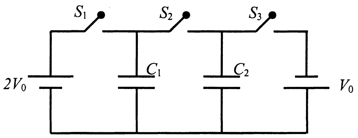
In the circuit displayed in the figure, two parallel plate capacitors each having capacitance are connected. Initially, switch is pressed to fully charge capacitor and then released. Subsequently, switch is pressed to charge capacitor . After some time, is released and then is pressed. After sufficient time has elapsed,
Options
A
the charge on the upper plate of is .
BCorrect
the charge on the upper plate of is .
C
the charge on the upper plate of is .
DCorrect
the charge on the upper plate of is .
Topics & Concepts
Step-by-Step Solution
To determine the charge on the upper plates of capacitors and , we follow the sequential switching operations step-by-step:
Step 1: Switch is closed and then opened
- The capacitor is connected across the DC source of emf , whose positive terminal is connected to the top wire and negative terminal to the bottom wire.
- Capacitor gets fully charged to a potential difference of .
- The charge on the upper plate of becomes:
- When is opened, capacitor retains this charge of on its upper plate.
Step 2: Switch is closed and then opened
- Closing connects the uncharged capacitor in parallel with .
- The total charge on the isolated top plates of and is conserved:
- Since both capacitors have identical capacitance , the common potential is:
- The charge on each capacitor's upper plate is distributed equally:
- When is opened, capacitor is completely isolated from the rest of the circuit. Therefore, its charge remains unchanged at:
Step 3: Switch is closed
- In the circuit diagram, the battery of emf in the rightmost branch is connected with its negative terminal at the top (short bar) and positive terminal at the bottom (long bar).
- When is closed, the capacitor is connected directly across this battery.
- After sufficient time has elapsed, the potential of the upper plate of relative to its lower plate becomes .
- Consequently, the steady-state charge on the upper plate of is:
Conclusion:
- The charge on the upper plate of is . (Option B)
- The charge on the upper plate of is . (Option D)
Therefore, the correct options are B and D.