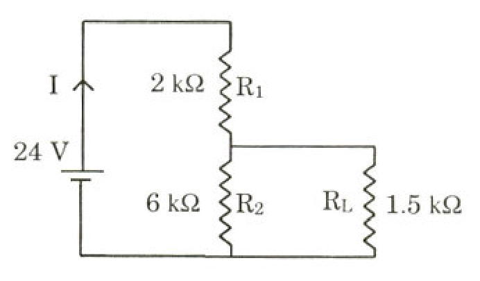
To determine the correct statements, we analyze the circuit step-by-step:
1. Initial Circuit Analysis
From the circuit diagram:
- The battery voltage is V=24 V.
- The resistors are R1=2 kΩ, R2=6 kΩ, and the load resistor is RL=1.5 kΩ.
- The resistor R2 is in parallel with the load resistor RL, and this combination is connected in series with R1.
The equivalent resistance of the parallel combination of R2 and RL is:
R2∥L=R2+RLR2RL=6+1.56×1.5=7.59=1.2 kΩ
The total equivalent resistance of the circuit connected to the battery is:
Req=R1+R2∥L=2 kΩ+1.2 kΩ=3.2 kΩ
Current through the battery:
I=ReqV=3.2 kΩ24 V=7.5 mA
Hence, Option (A) is correct.
Potential difference across RL:
The voltage across RL is the same as the voltage across the parallel combination:
VL=I×R2∥L=7.5 mA×1.2 kΩ=9 V
Since VL=9 V=18 V, Option (B) is incorrect.
Ratio of powers dissipated in R1 and R2:
The voltage across R1 is:
V1=V−VL=24 V−9 V=15 V
The power dissipated in R1 is:
P1=R1V12=2 kΩ152=2225 mW=112.5 mW
The power dissipated in R2 is:
P2=R2VL2=6 kΩ92=681 mW=13.5 mW
The ratio of powers is:
P2P1=13.5112.5=325=3
Hence, Option (C) is incorrect.
2. When R1 and R2 are Interchanged
Now, the values are:
- R1′=6 kΩ
- R2′=2 kΩ
- RL=1.5 kΩ
The new equivalent resistance of the parallel combination of R2′ and RL is:
R2′∥L=R2′+RLR2′RL=2+1.52×1.5=3.53=76 kΩ
The total equivalent resistance becomes:
Req′=R1′+R2′∥L=6+76=748 kΩ
Using the voltage divider formula, the new potential difference across RL is:
VL′=V×Req′R2′∥L=24 V×74876=24×486=3 V
The ratio of the new power dissipated in RL to the initial power is:
PLPL′=RLVL2RL(VL′)2=(VLVL′)2=(9 V3 V)2=(31)2=91
Thus, the power dissipated in RL decreases by a factor of 9.
Hence, Option (D) is correct.
Conclusion
The correct options are A and D.